
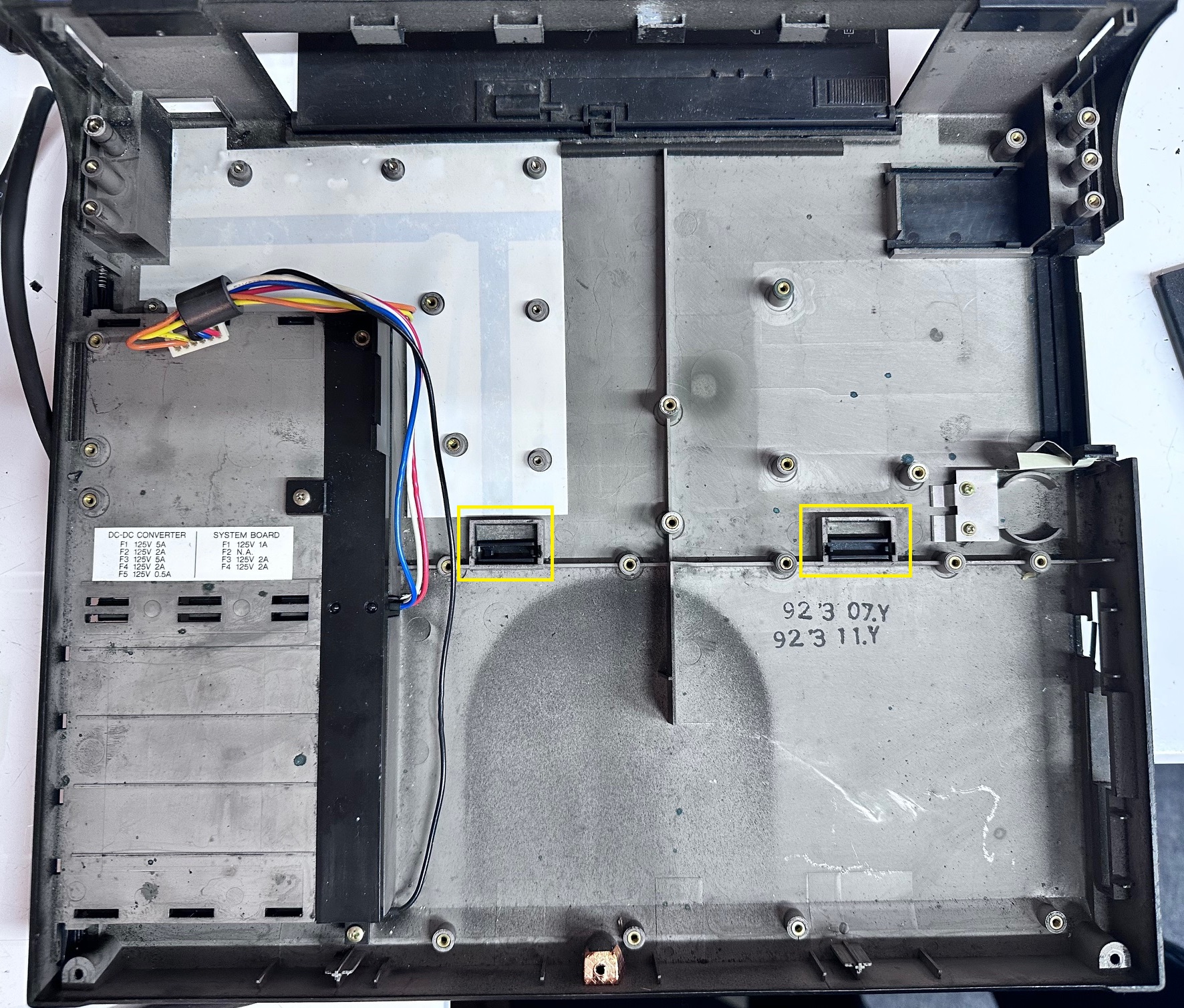
This is a massive, stange, outlier in IBM's journey into portable personal computers. CL for 'Color Laptop' and 57 for....... fuck knows. The type is 8554 and it runs MCA bus.
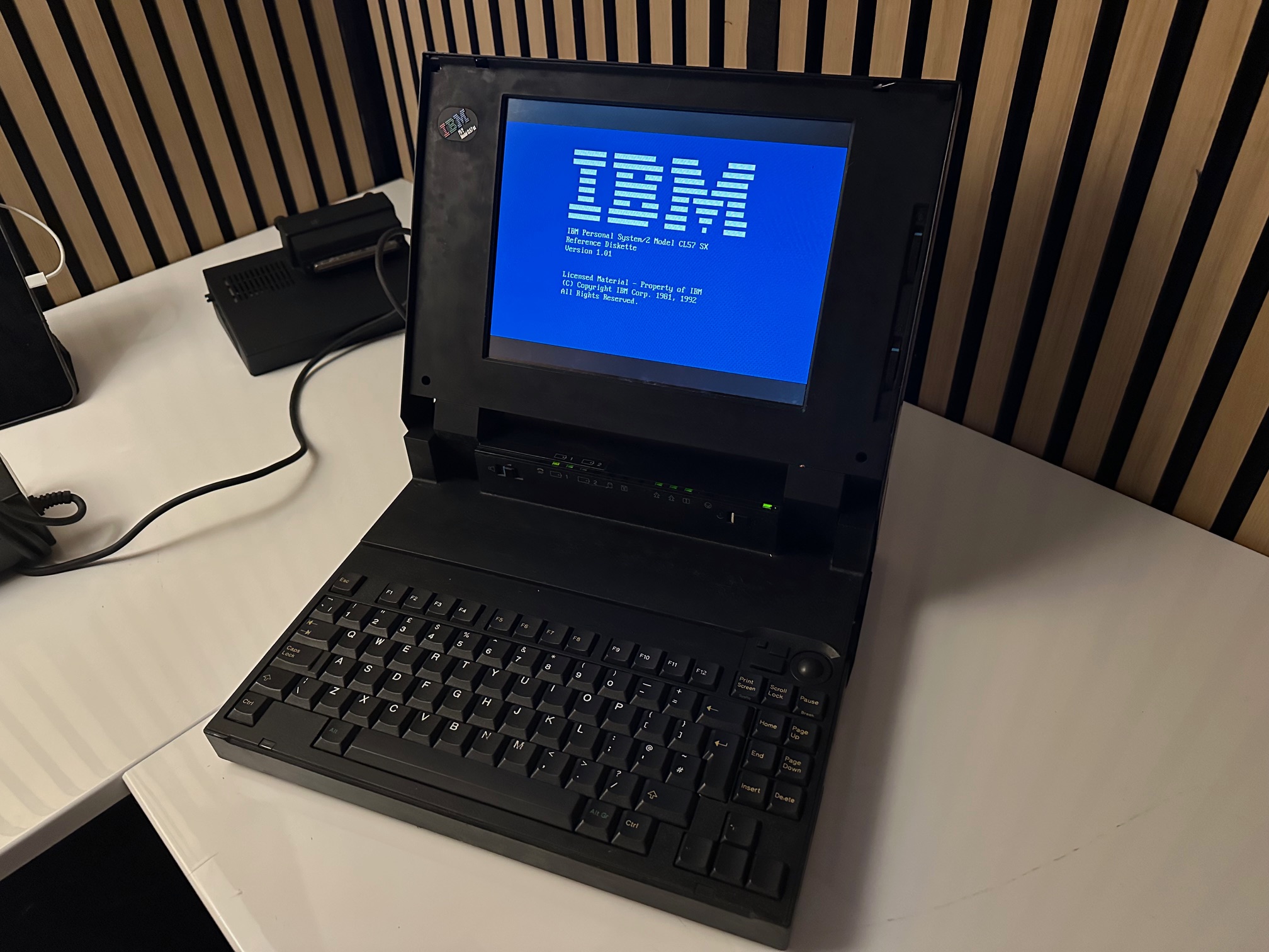
The CL57 was released under the 'note' model range, so I'm including it here, even though it's not a note and it's not remotely like a notebook. It's definitely a desktop replacement, otherwise known by IBM as a 'Multistation'.
Some sources state this machine started as a Model N27sx - a 'for fun' IBM Japan design for domestic japanese market. I can't find much source material that this is true though. Apparently, the CPU was downgraded from a 486 to a 386 so as to not compete with other PS/2 machines. Supposedly there are some hidden clues on the machines that despite it's international 85xx model designation, the plant ID is 97 which is IBM Japan Entry Systems factory in Fujisawa.
| Model | IBM Thinkpad |
| Machine Types | 8554 |
| Release Timeframe | Sold from April 1992 for around 10 months. |
| Preceded by | Nothing like it came before. Spiritually, perhaps the Japanese Multistations or the L40 SX Laptop. (This is the Color Laptop CL) |
| Superceded by | N27SX miniturised the backlight and 700C capitalised on the technology |
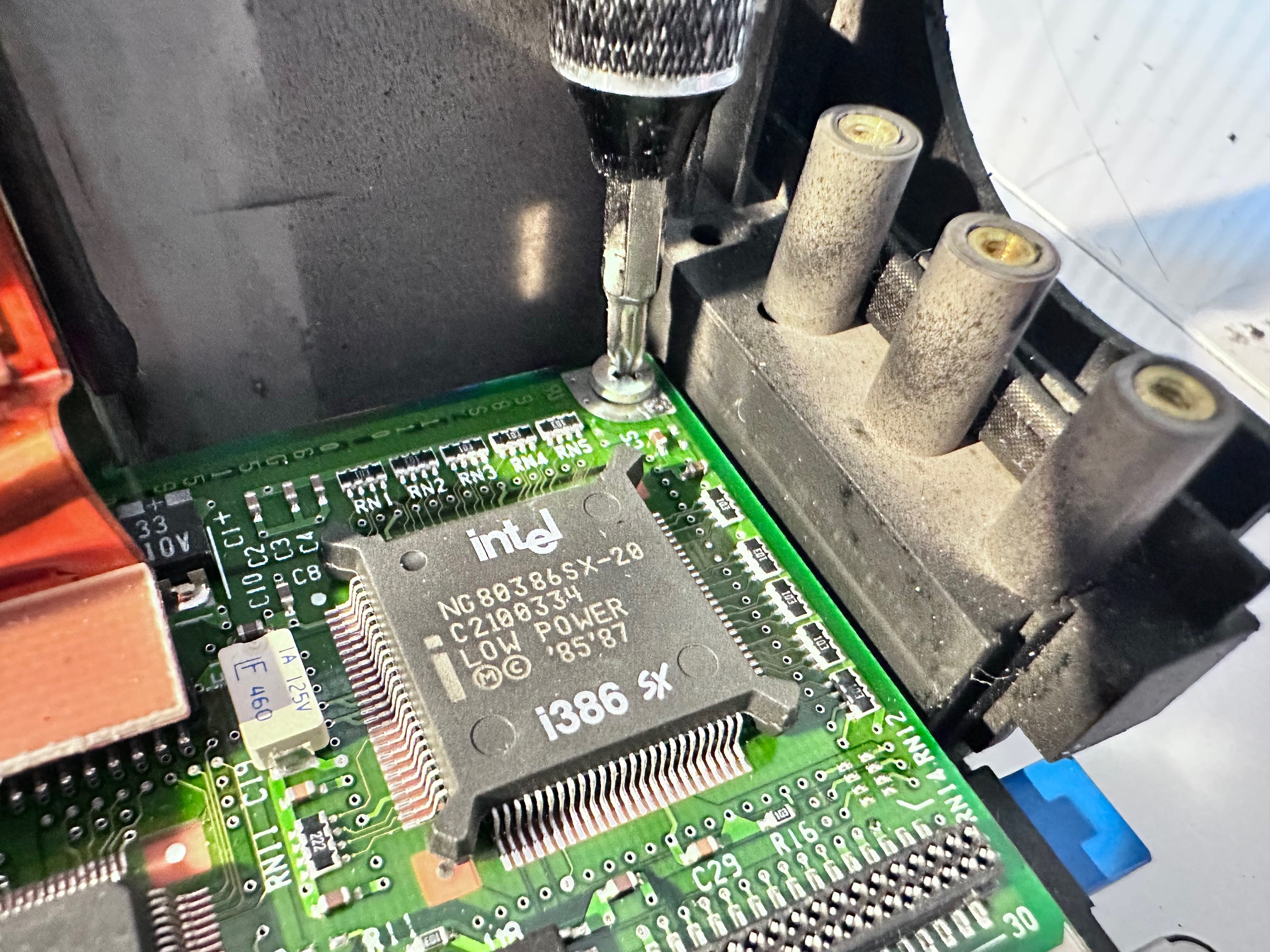
| Motherboard Specs | 386SX processor at 20 MHz (an IBM downgrade) with 2-16Mb of RAM |
| Display Specs | 10.4" colour TFT LCD display using VGA (640x480) resolution |
I need to go and re-read the All About Thinkpad book but there is at least a whole chapter about how the display inside the CL57 (10.4-inch TFT colour LCD with 640 x 480 VGA resolution) was so important to the success of the Thinkpad. From memory, it was first found in the CL57 (April 1992), the PS/2e (July 1993) and the 700C (October 1992) - with the far more portable notebook 700C having the most use for such a bright, sharp, high-referesh, low power, flat and portable display. These were jointly manufactered by IBM and Toshiba who agreed to split the purchase of the first production run 50/50 until IBM found they could sell almost all of them far easier than they thought.
Apparently, the reason the CL57 is so big is that the 10.4 inch TFT display still required a large powerful backlight, which meant the lid had to be huge. It appears later versions of the Toshiba-made TFT display became smaller, first seen in the C23V 'proper notebook' and then perfected in the C52/700C.
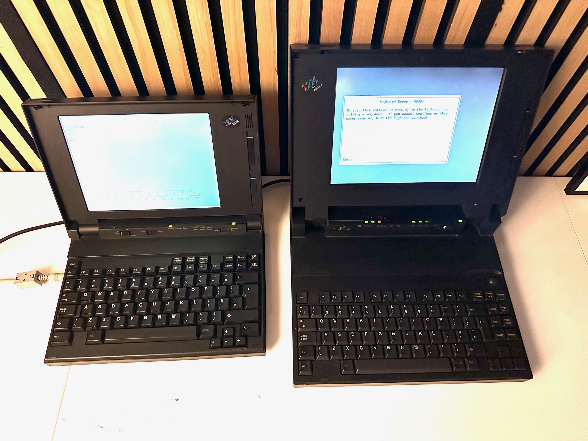
Here is a size comparison showing the 5523 PS/55 Note on the left and the CL57 on the right. The 5523 would have given it's right shift key for the TFT panel in the CL57 but it would have more than doubled the price and, at the time, would have never fit.


The CL57's 'last knockings' of IBM Japan's 'desktop replacement' Multistation design is almost completely unique, although it shares a look similar to that of the possibly-vaporware, Japan-only PS/55 Power (PC) Laptop EWS - which also feels like a skunkworks project.
 Was this the CL57's illegitimate step-son-in-law? The Power PC EWS?
Note how the EWS has brightness and contrast buttons from a 700T, a full size 'proper keyboard (which would have made it noticably wider than other machines), CD-ROM, stereo speakers and what looks like a blueprint of the millenium falcon??
For fun I lined 1991's L40 SX against 1992's CL57 SX and if you look closely, considering they individually evolved from very different spaces, you can spot a lot of similarities:


Teardown
1 - Remove both batteries:
2/3 Remove bottom 3 screws:
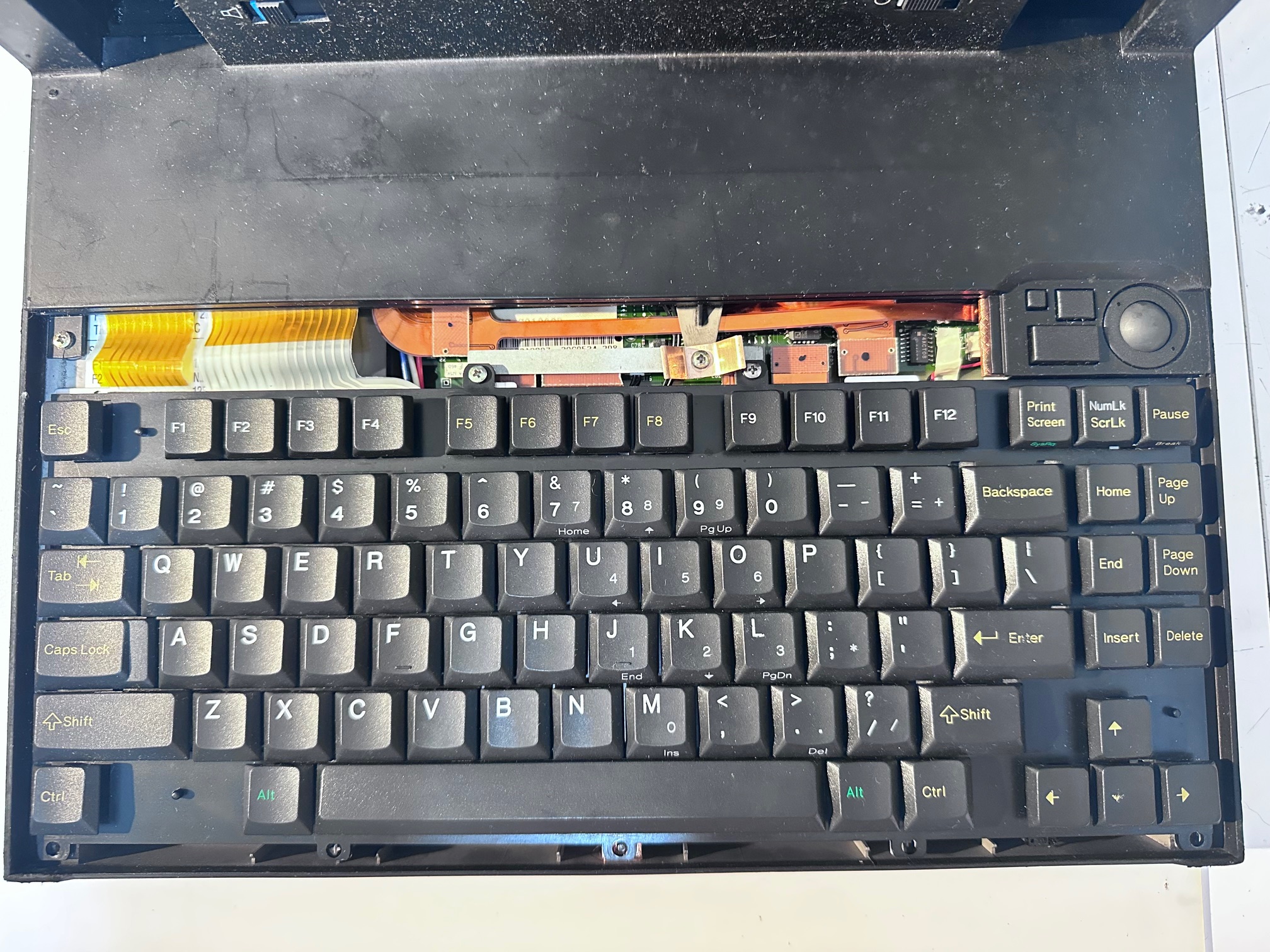
4 - Remove keyboard surround:
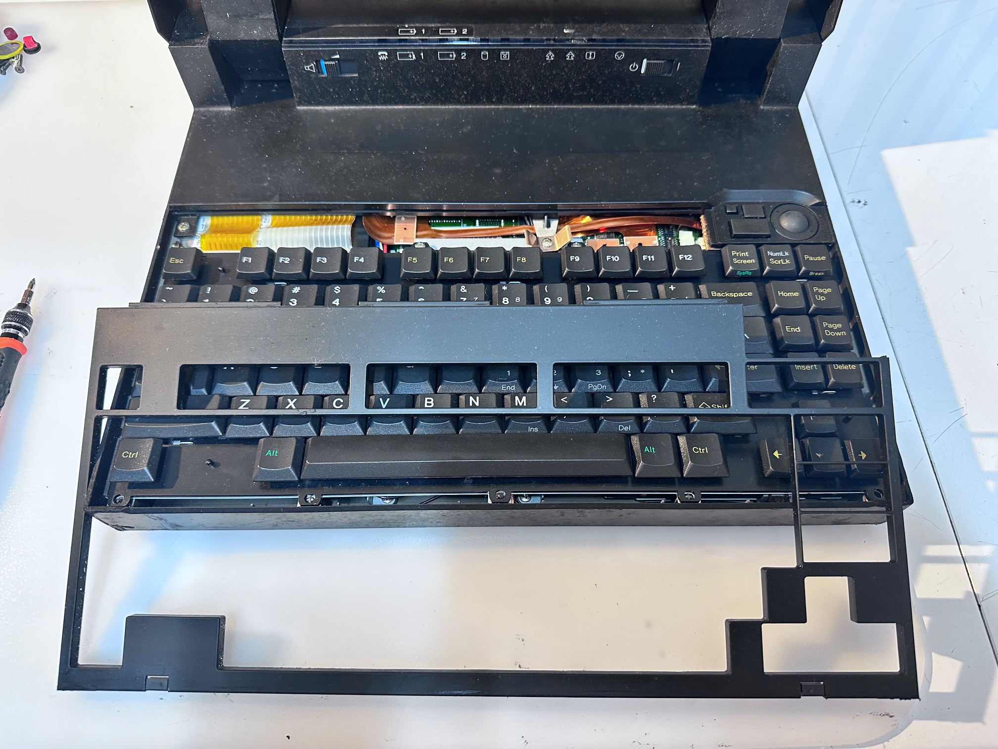
5 - Remove the 4 screws under keyboard cover:
6 - Remove small metal plate:
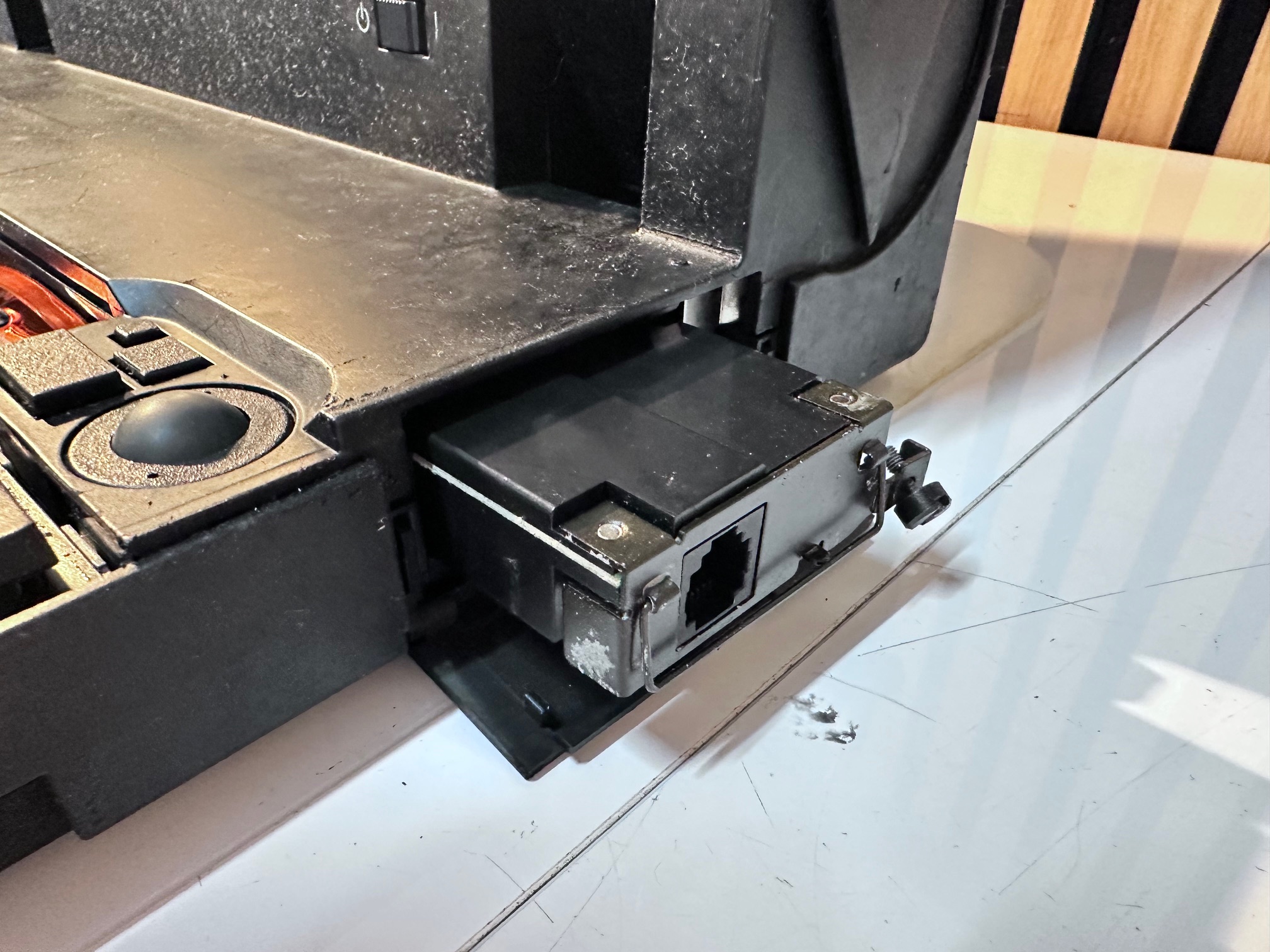
7 - Unscrew modem from right side:
8 - Remove plastic covers either side of LED bezel:
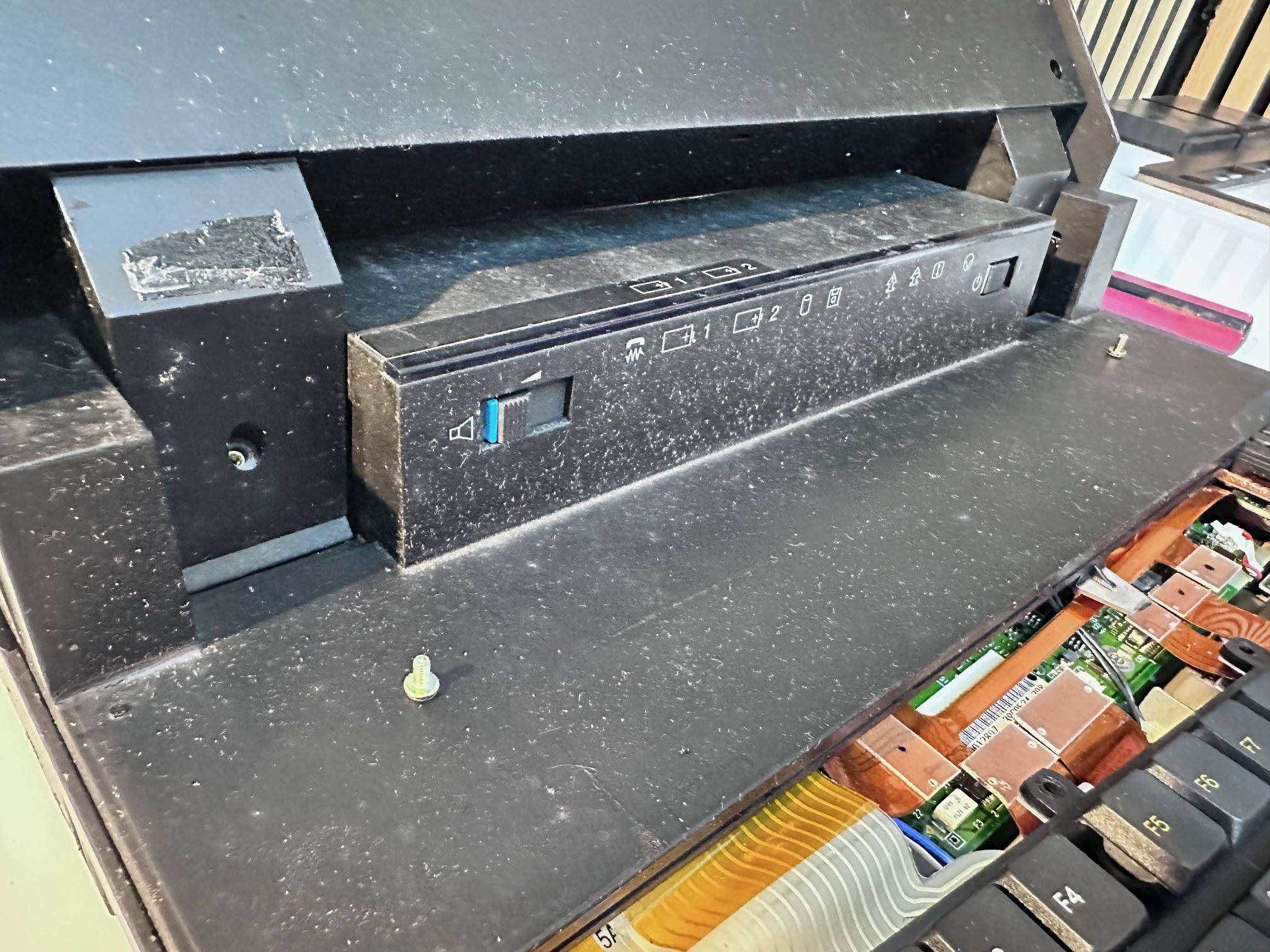
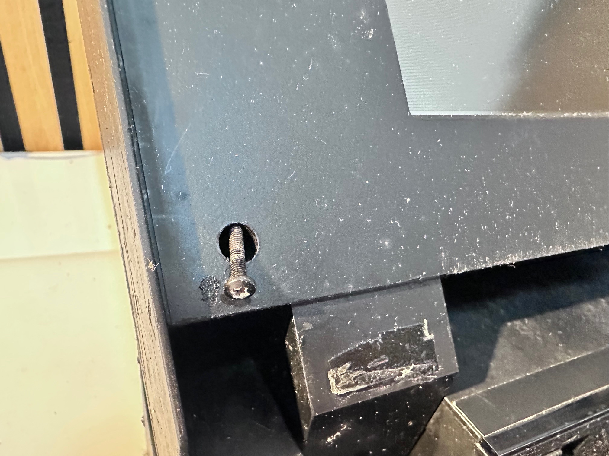
9 - Remove both screws:
10 - Remove screws either side of the bottom of the LCD bezel
11 - Remove both rubber bungs at top of bezel and both screws underneath
12 - Close lid and remove the back of the lid
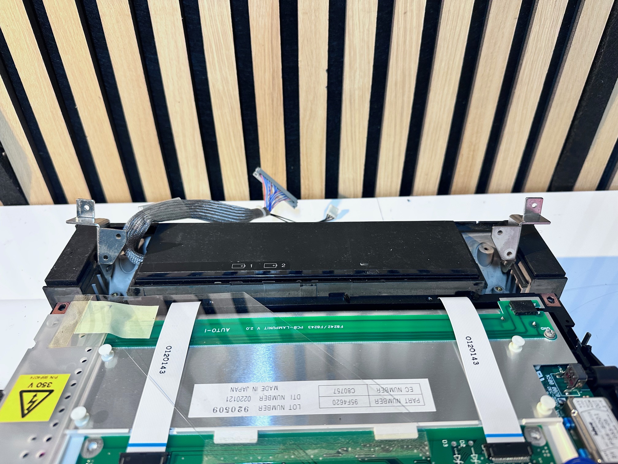
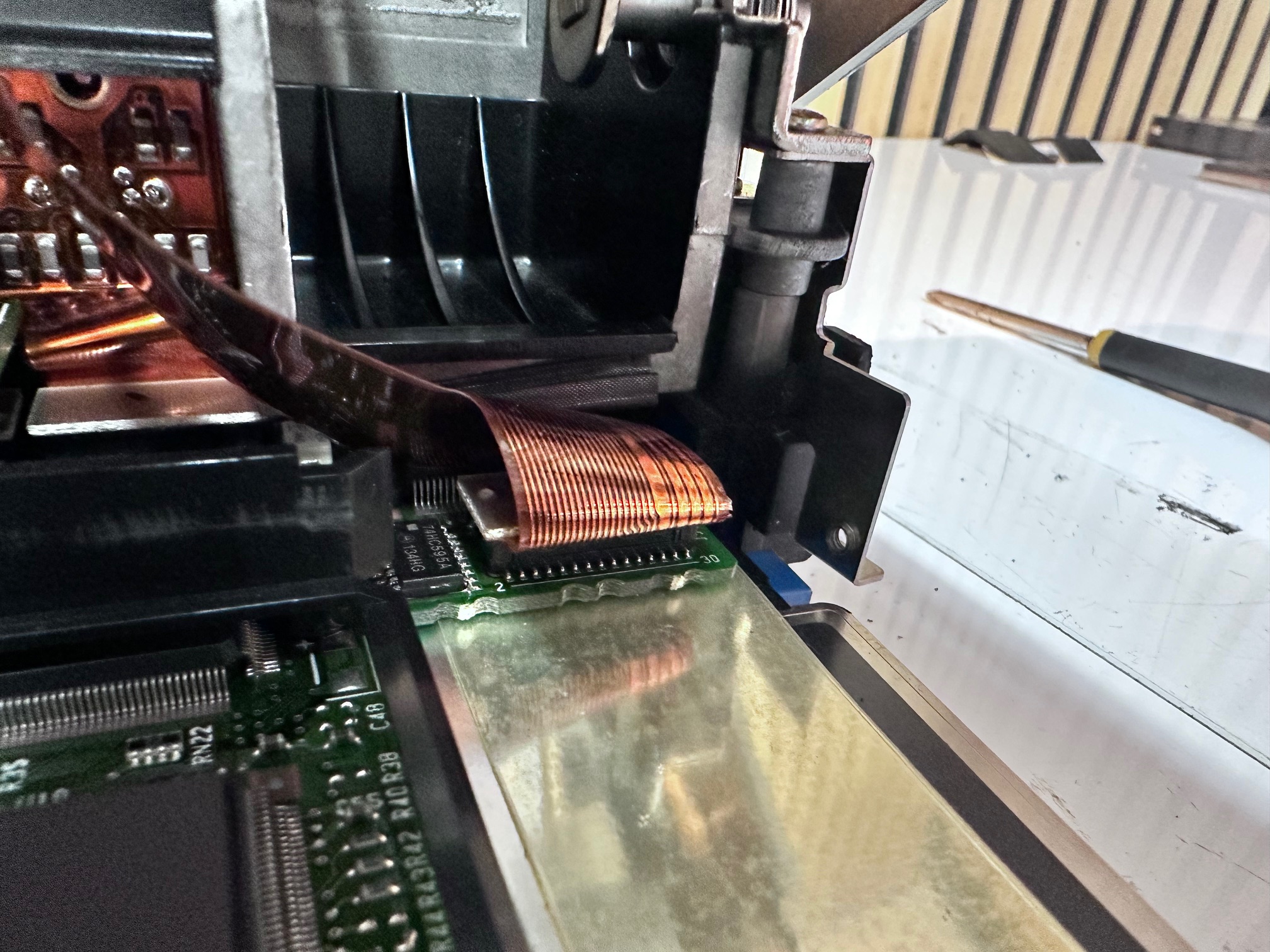
11/12/13 - Here is a close up of the back of the TFT:
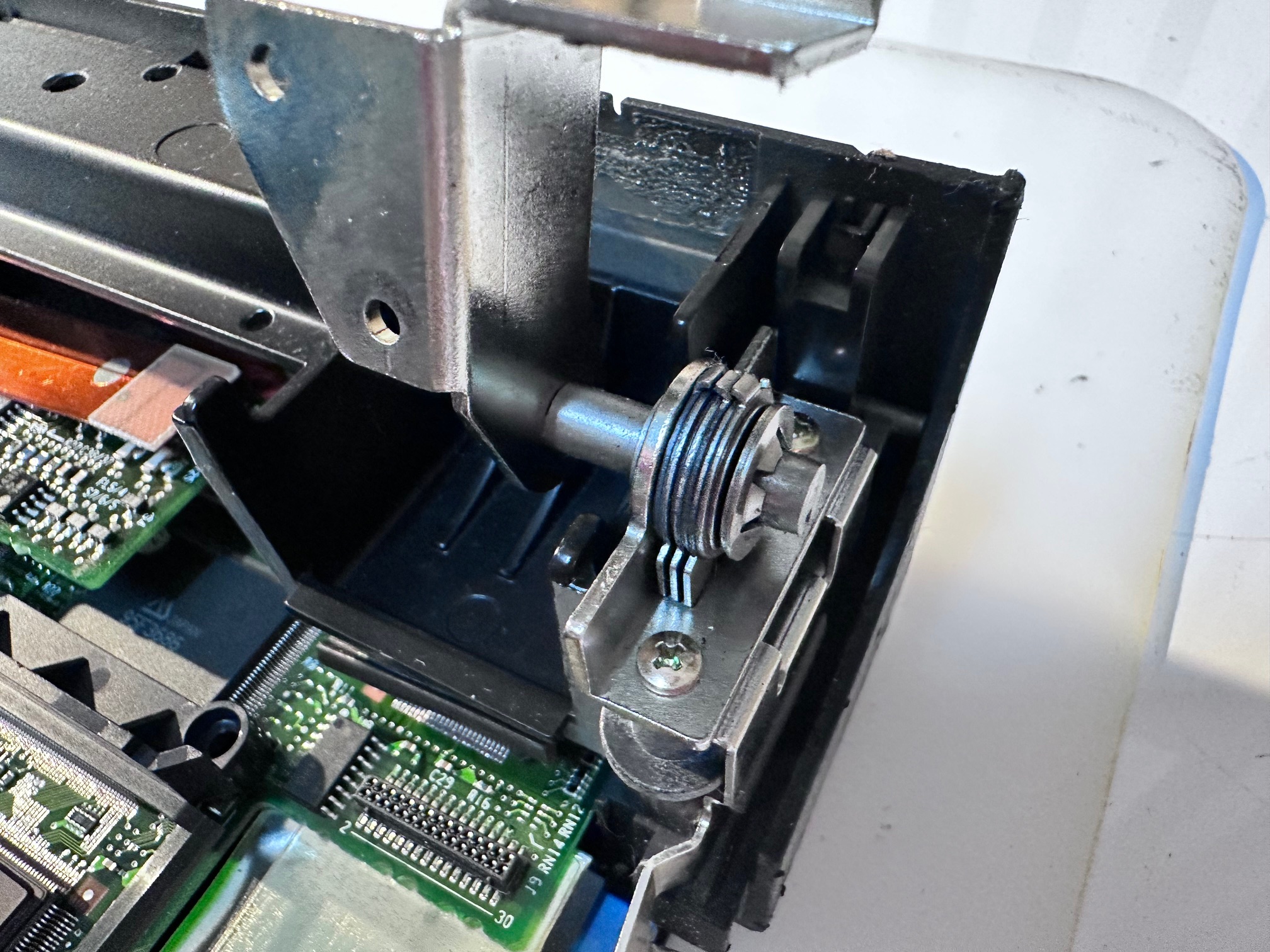
And here is a close up of the base of the hinges:
16 - Disconnect video and power cable from the back of the LCD assembly:
17 - Remove 2 right hinge screws:
18 - Remove 2 left hing screws:
19 - Pull hinges up and back:
20 - Lift forward and away entire front LCD/bezel assembly:
21 - Pull up trackball cable:
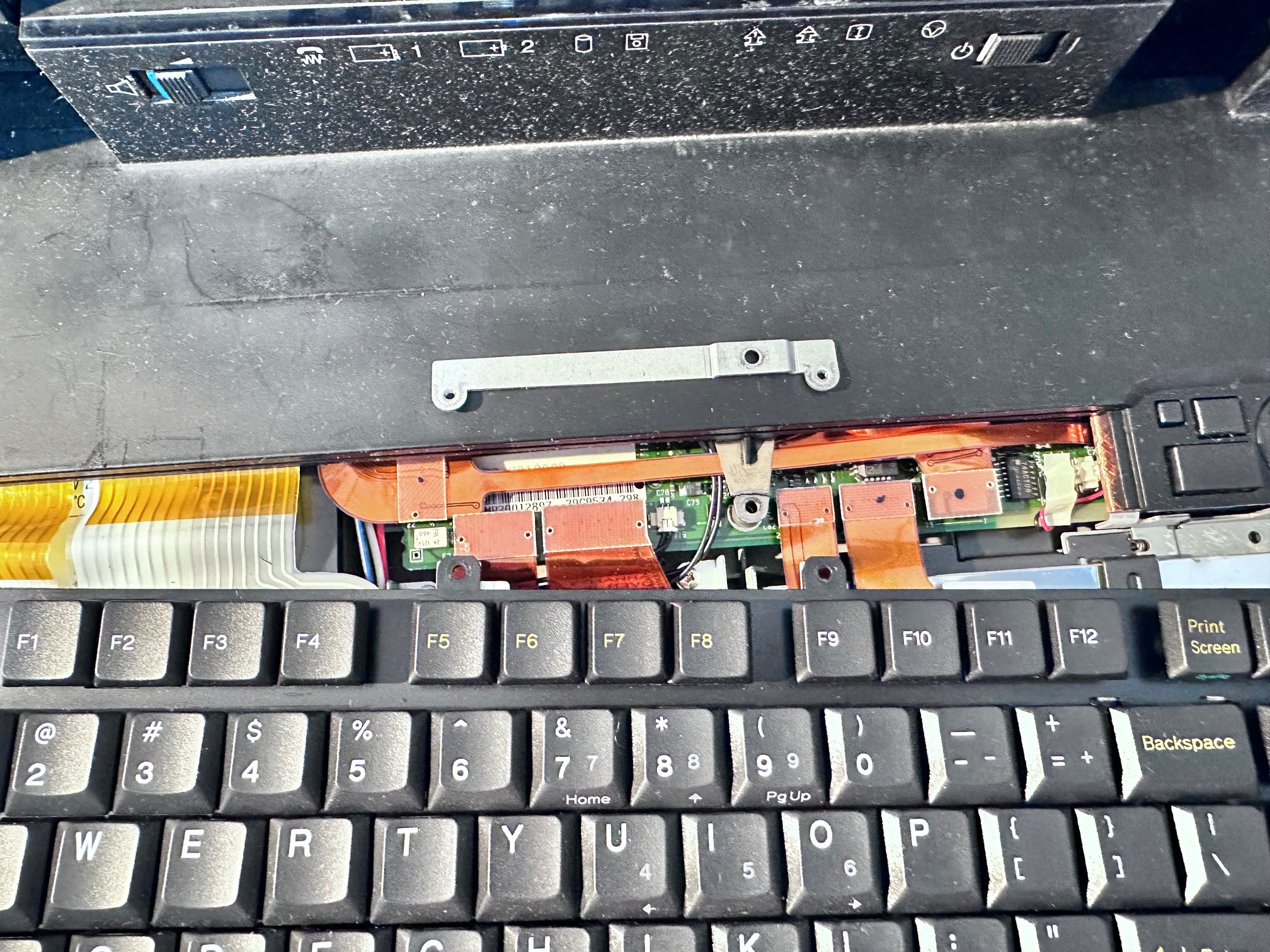
22 - Remove tape off the top of the two keyboard ribbons and pull out the friction connection cables:
21 - Remove second trackball connector:
24 - Push up clip hidden above all the back/rear connectors:
25 - Disconnect ribbon towards the back to disconnect LED indicator panel:
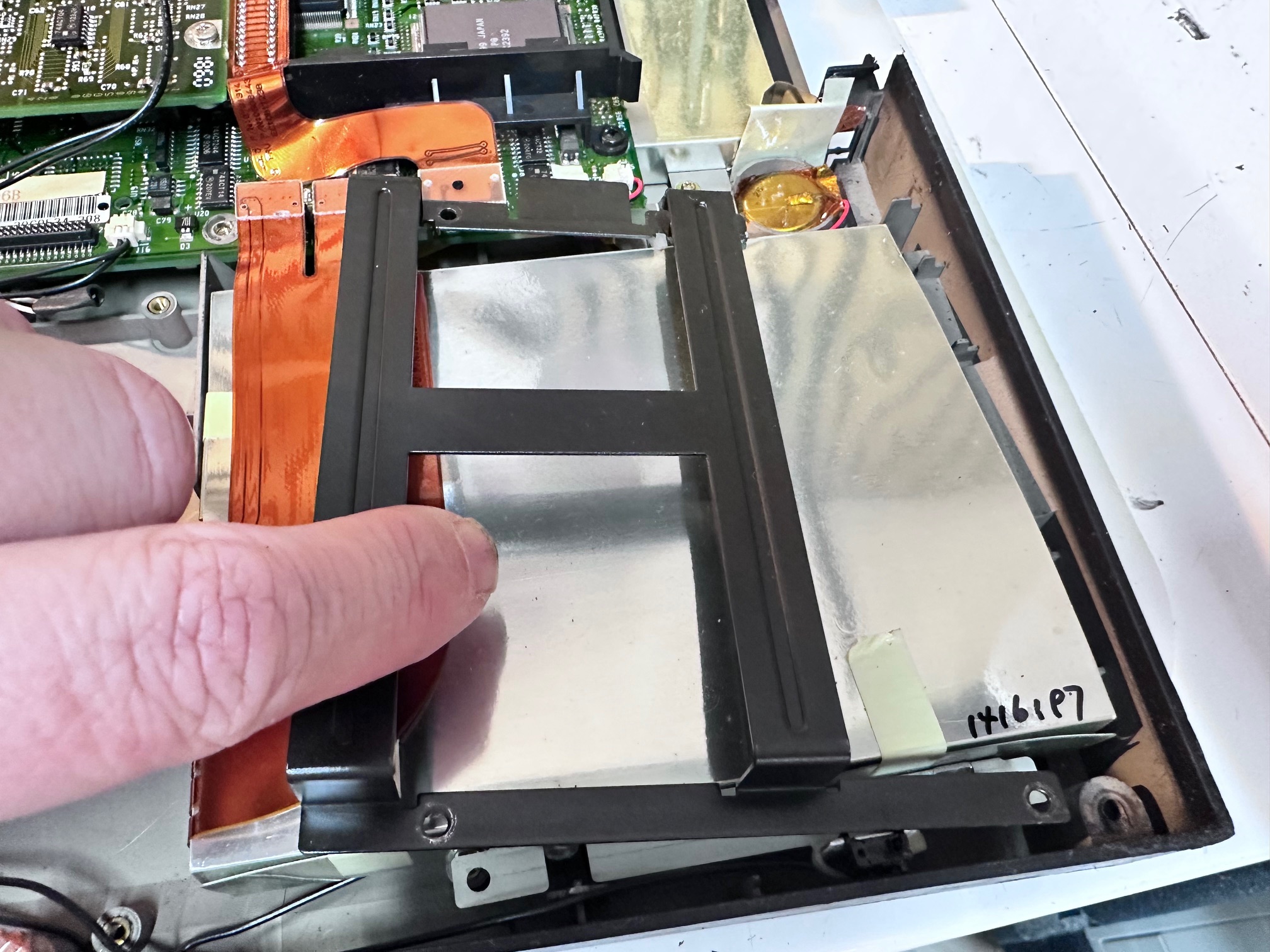
26 - Remove 4 screws holding HDD caddy in place:
27 - Unplug the 2 black connectors under the LED bezel:

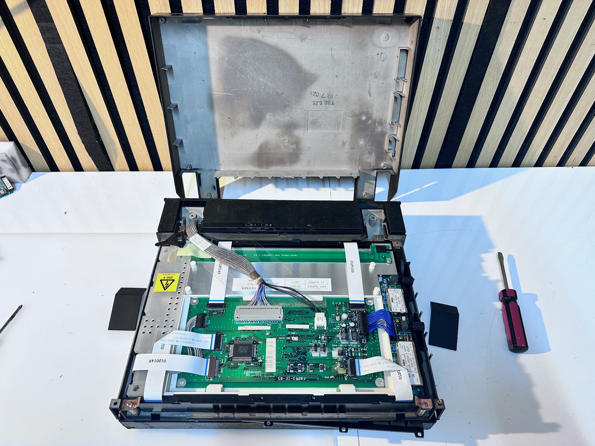
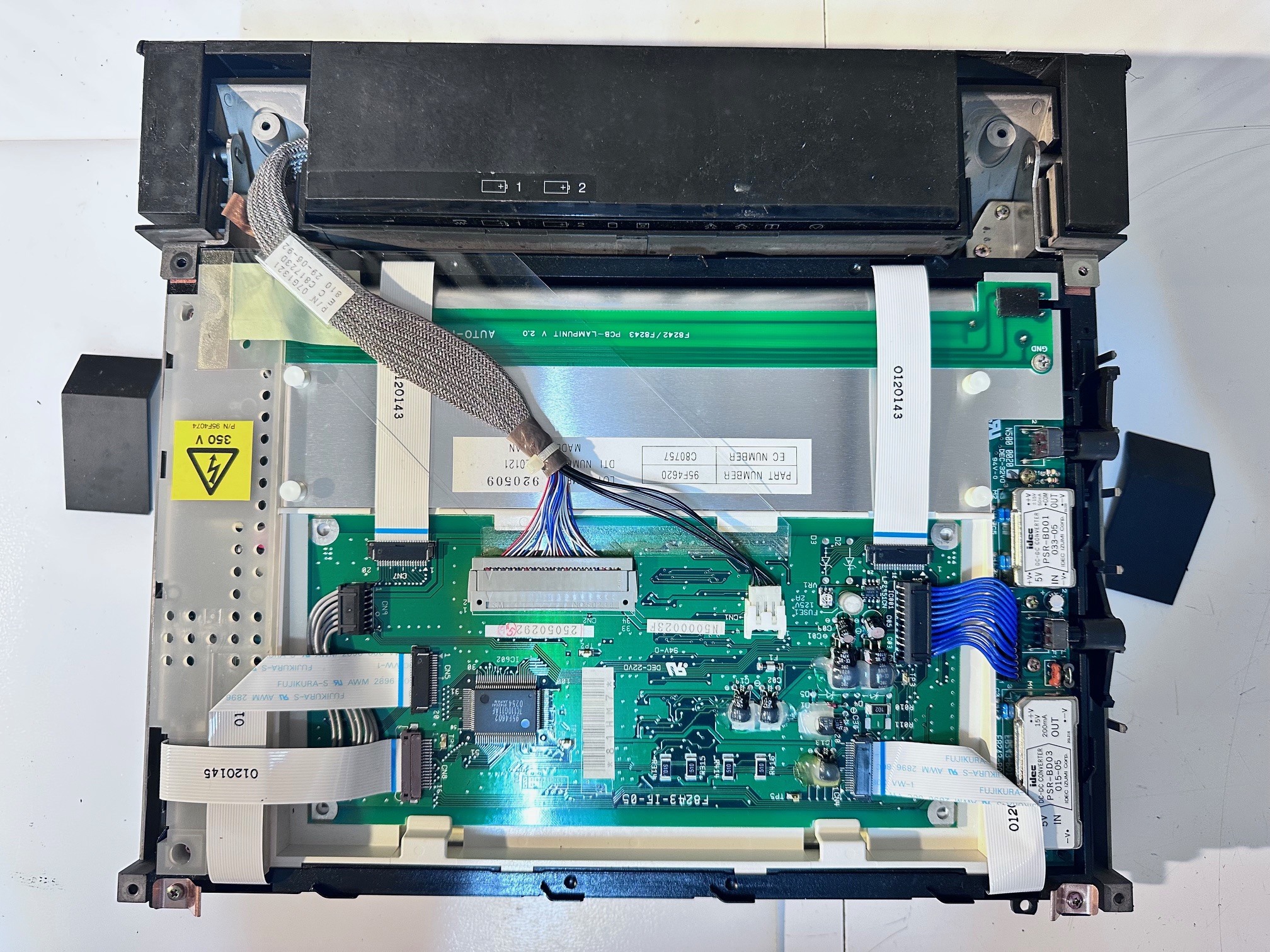
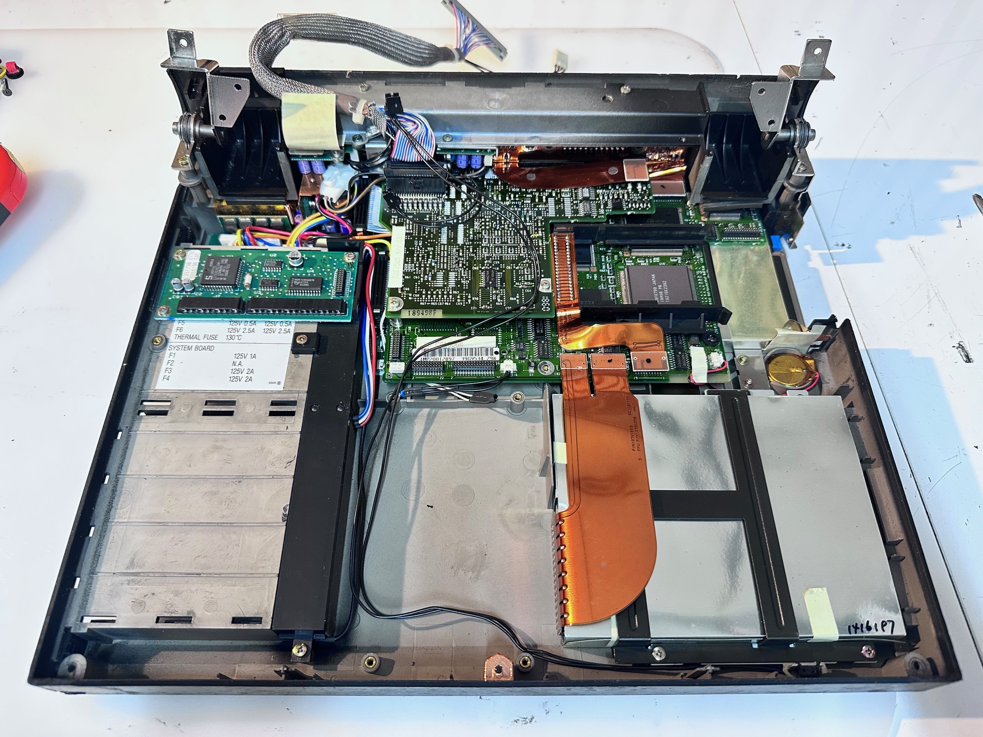
28 - And here is a picture of the base with the top section removed:
29 - Remove keyboard PCB:
30 - Remove 3 screws ontop of FDD plastic bracket:
31 - Lift out FDD (no pic)
32 - Remove 5 screws on metal panel between hinges:
33 - Remove 2 screws holding down left hinge:
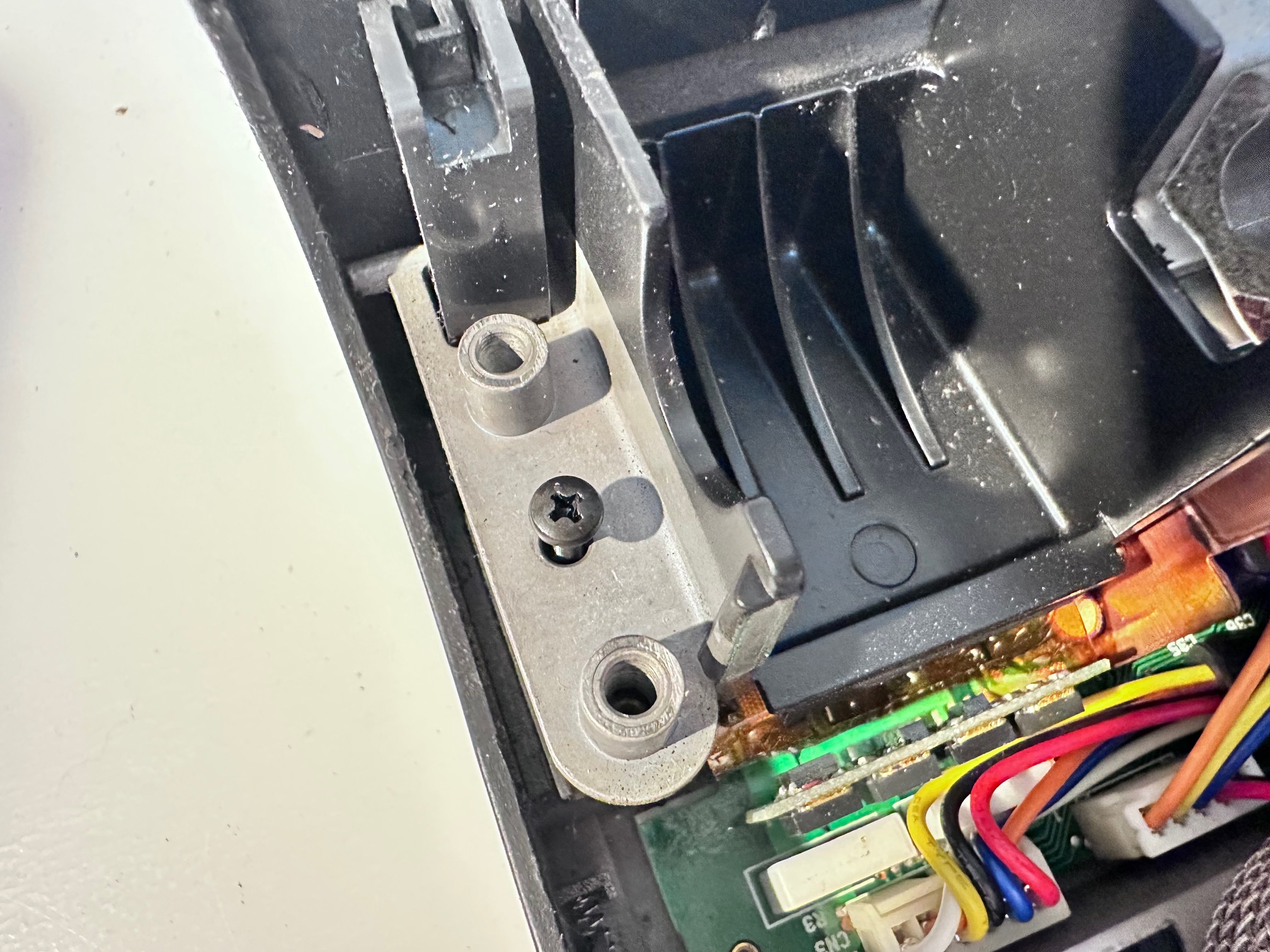
34 - Remove 2 screws holding down right hinge:
35 - Remove black screw under left hinge
36 - Remove black screw under right hinge
37 - Remove right bracket
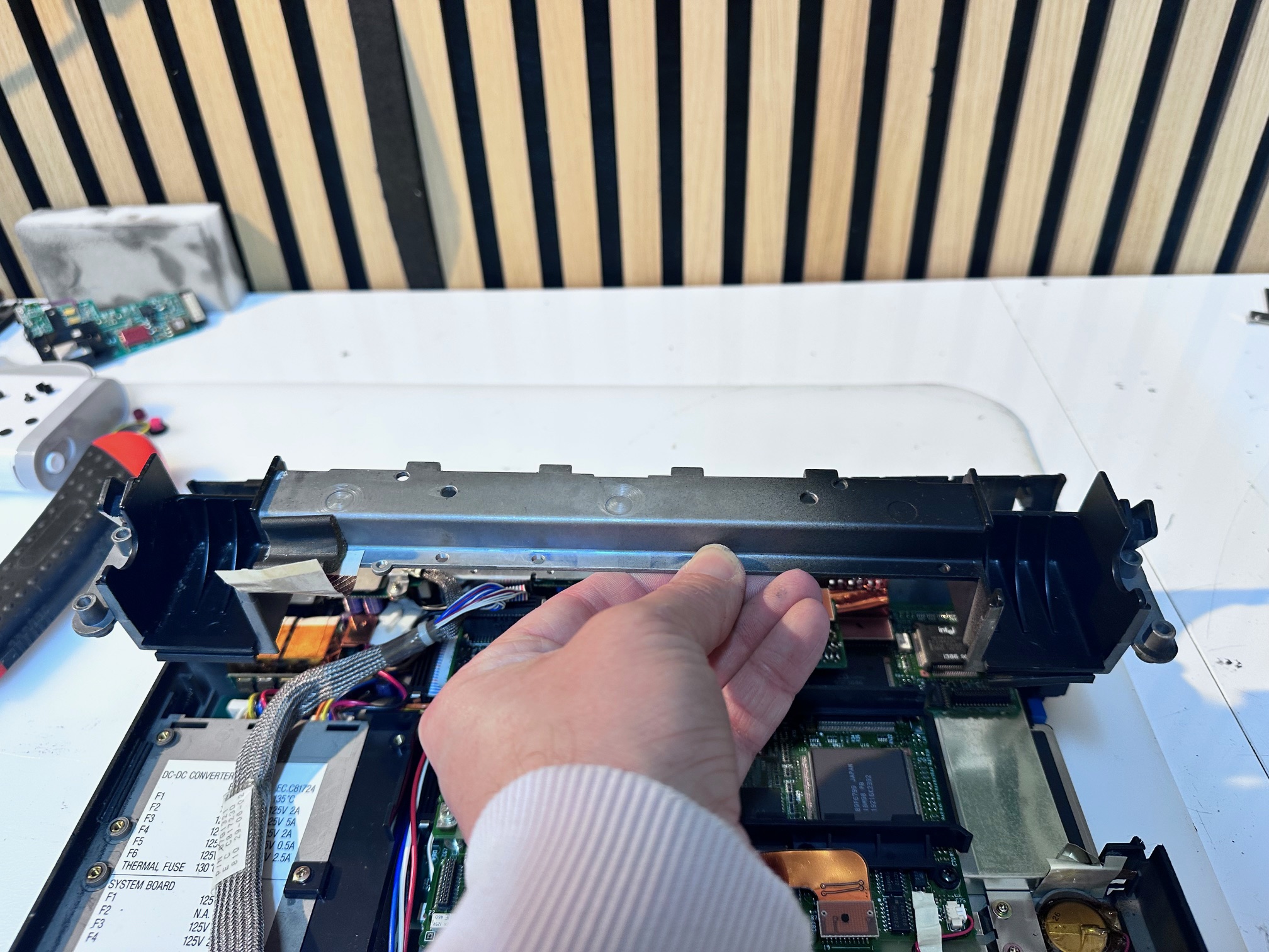
38 - Lift off heavy top metal bracket:
39 - Unplug and disconnect power/DC board:
40 - Unplug modem connector ribbon plug:
41 - Unplug ribbon to rear panel:
42 - Remove 2 screws:
43 - Lift off sub board:
44 - Remove 3 screws (no screw top right) of the plastic cage which holds modem:
45 - Remove both metal standoffs
46 - Remove both screws on battery bracket and unplug the white/left battery connector:
47 - Unplug top blue/red/white connector:
48 - Remove screw under the last cable:
49 - Remove back right screw:
50 - Pull up entire motherboard:
51 - Remove 2 metal standoffs:
52 - Remove final power board with its 8 small screws:

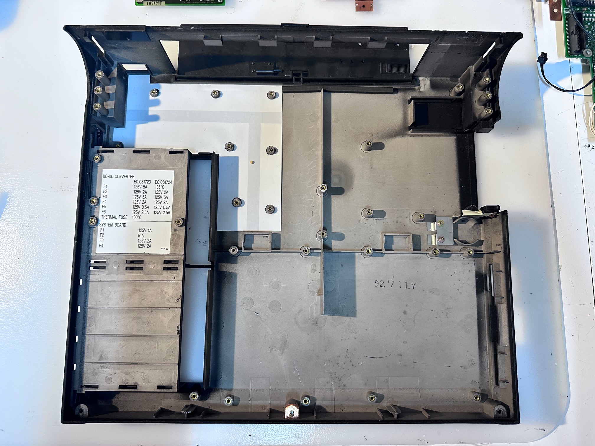
53 - Admire the empty base!!!!:
Board Recapping
The CL57 does have a few boards inside which each need recapping. It's not a tough or tricky job. I try to replace all surface-mounted caps with solid state equivilents - even though they have a much lower ESR rating I did not detect any issues in the CL57 running on a bunch of solid caps.
There are two power-related boards - this one at the very bottom has the power connector onboard and as you can see has a bunch of through-hole electrolytic caps to replace:
3 x 47uf / 16v
4 x 15uf / 25v
2 x 1.5uf / 25v
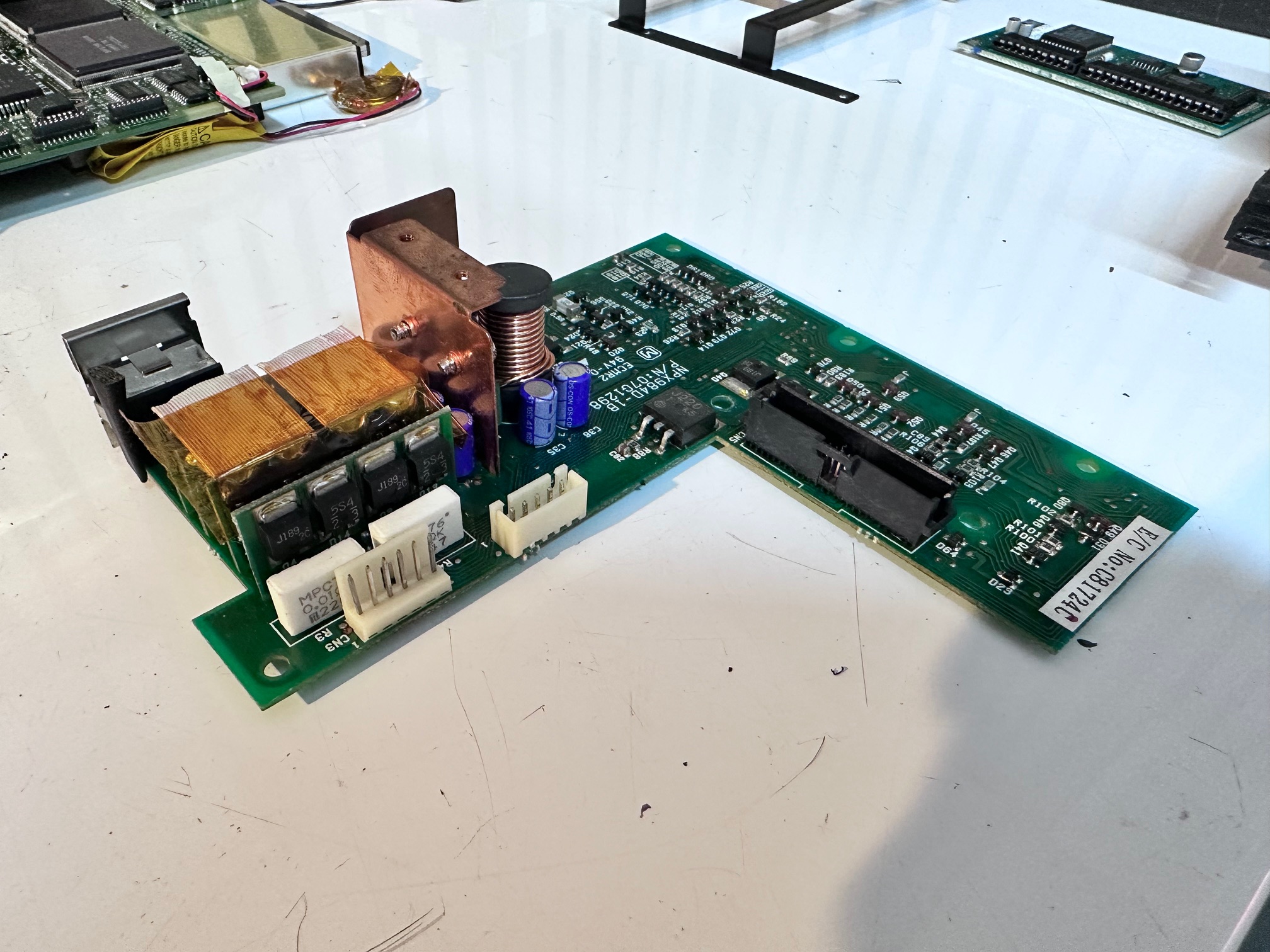

Here is the layout of the capacitors:

There are 2 fuses on this board, on the bottom, which should be checked for continuity:


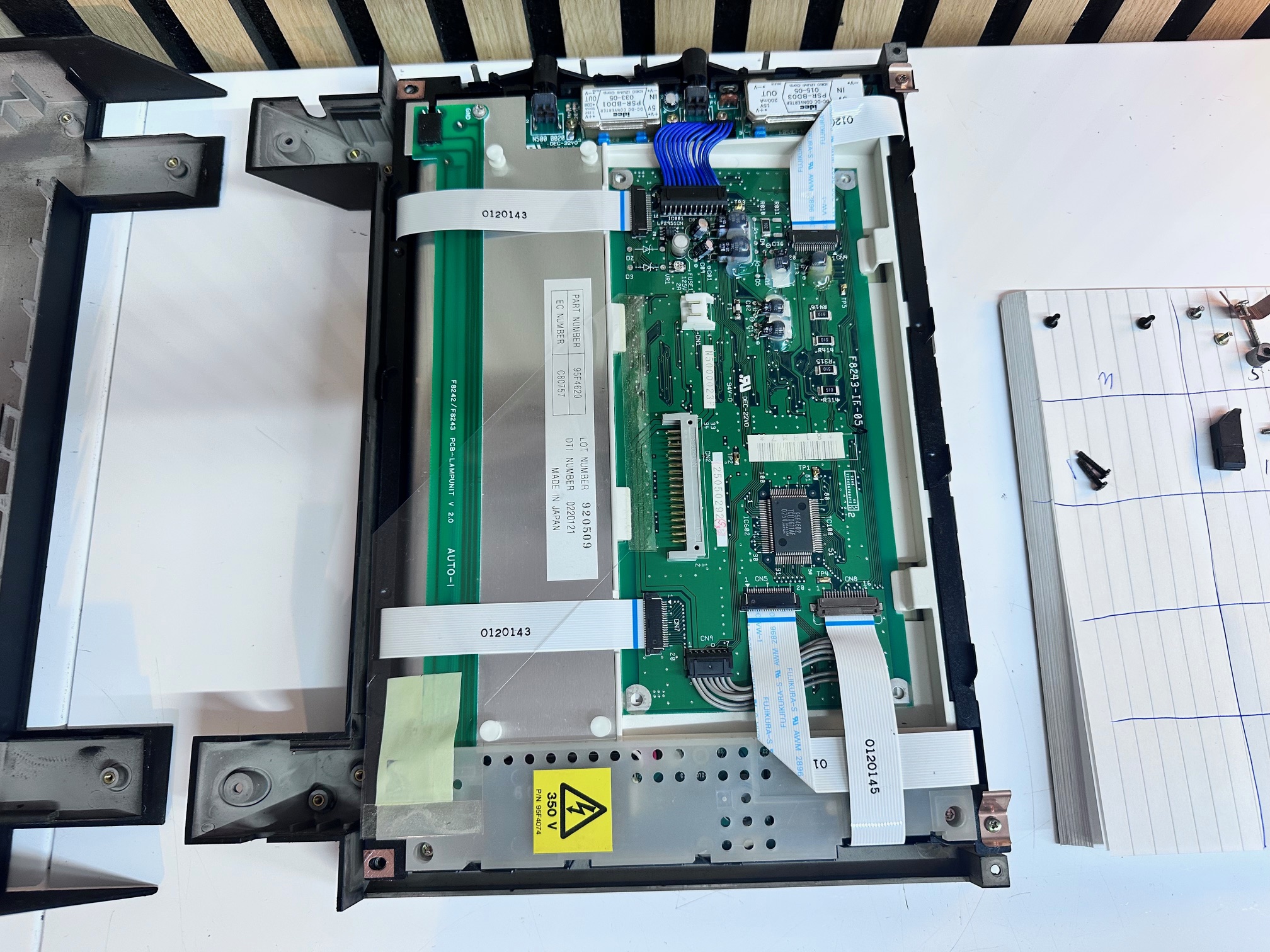
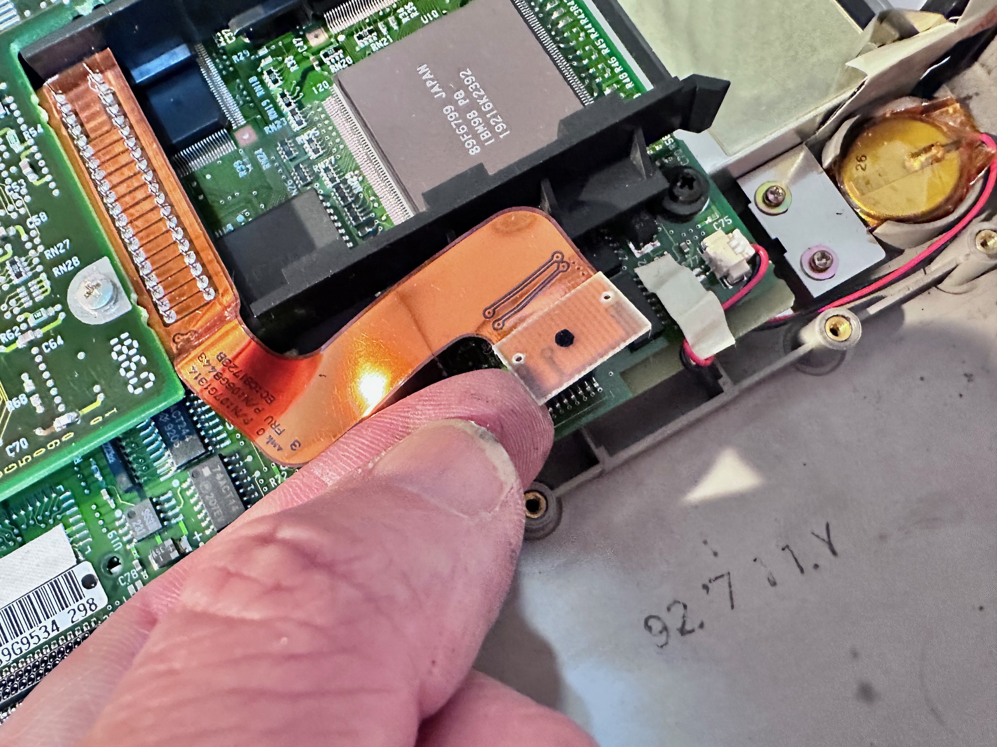
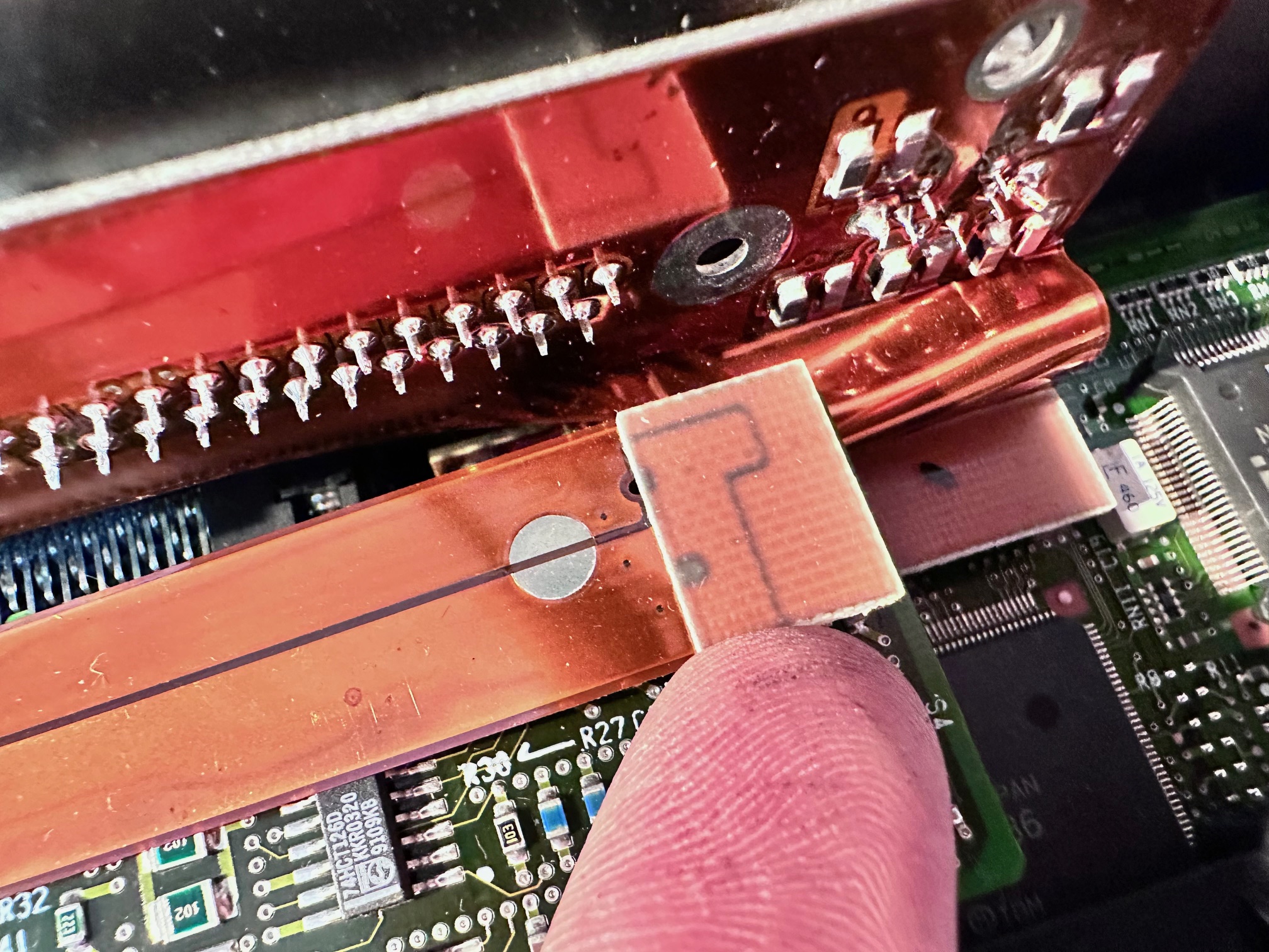
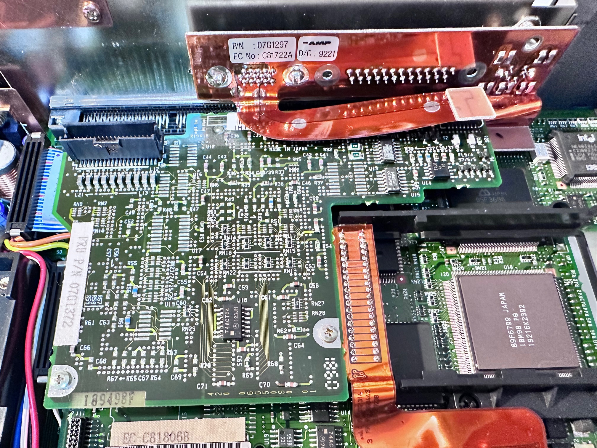
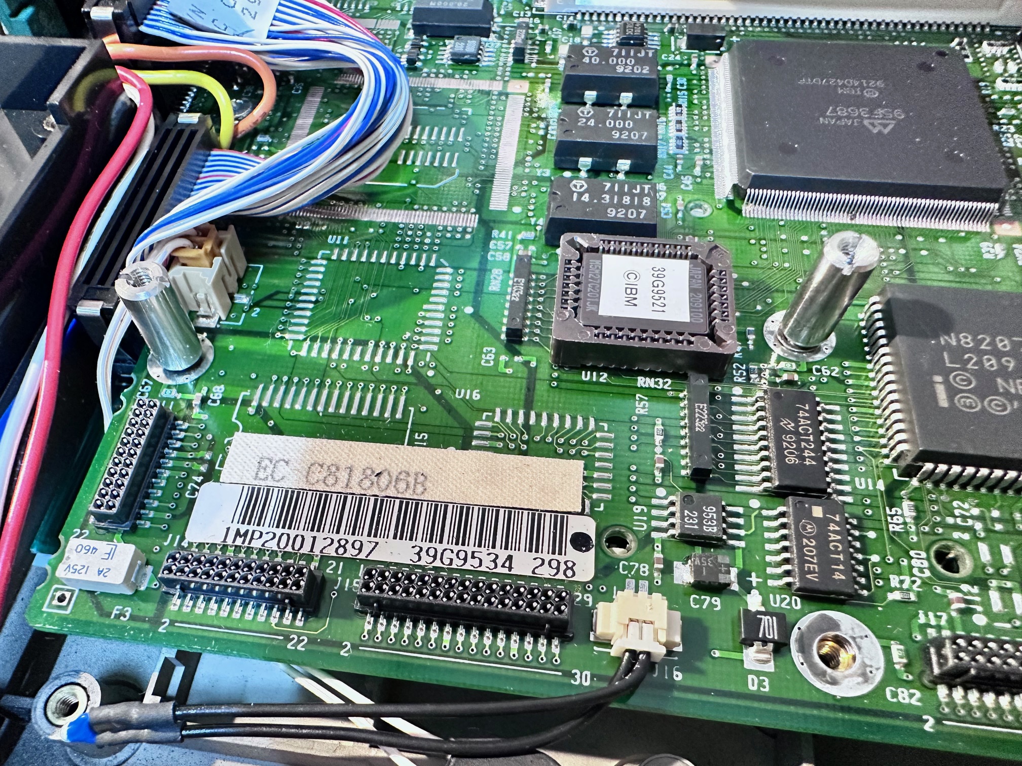
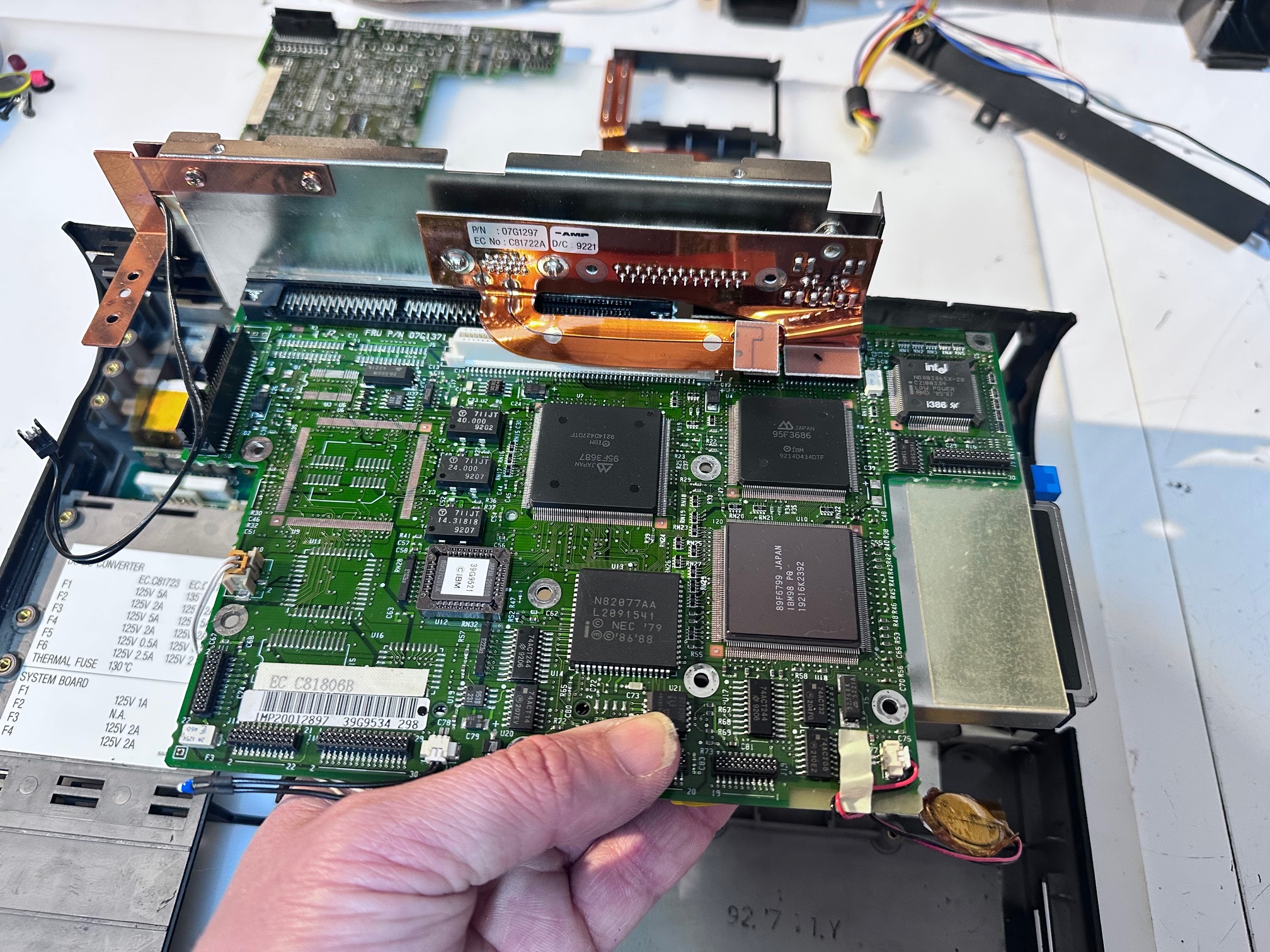
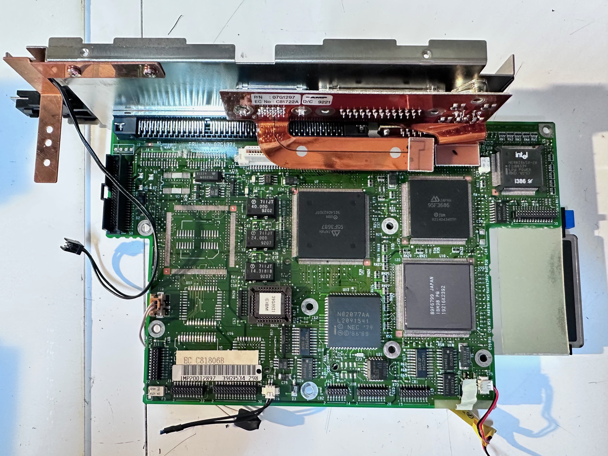
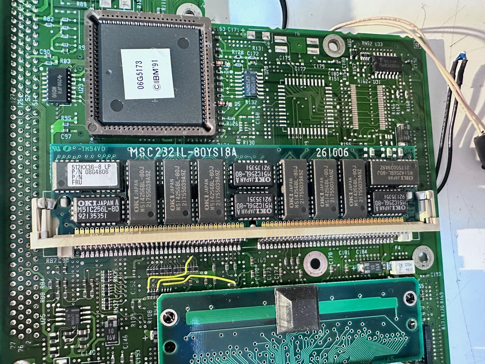
The motherboard doesn't have any electrolytic caps of any sort. So nothing to change, but I took a couple of photos for reference. Note the IC DRAM daughterboard is on the bottom...
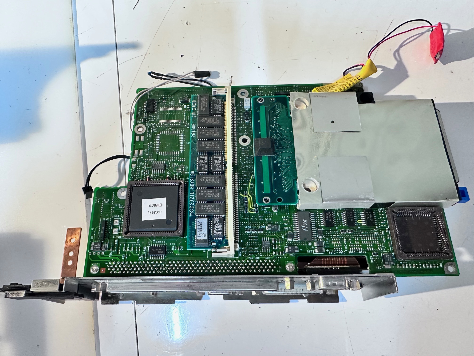
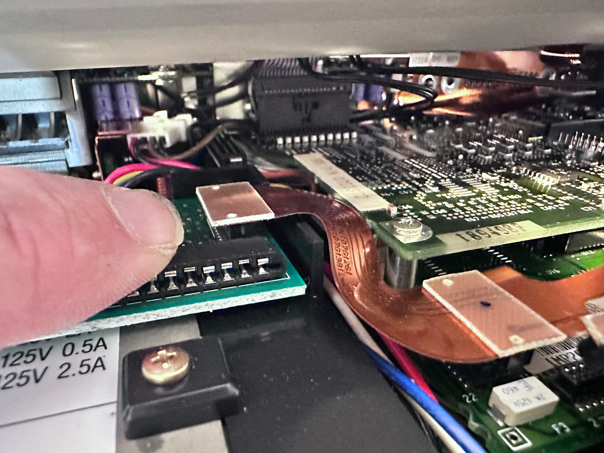
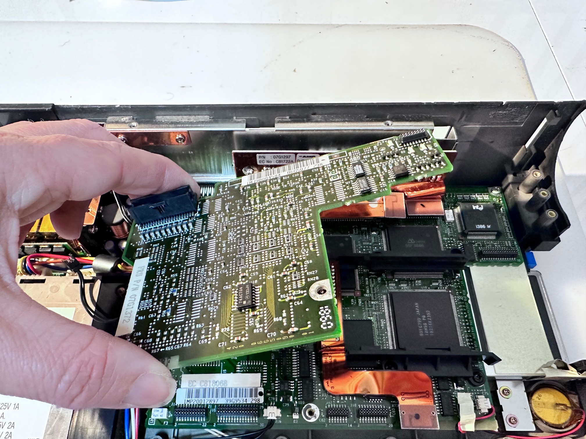
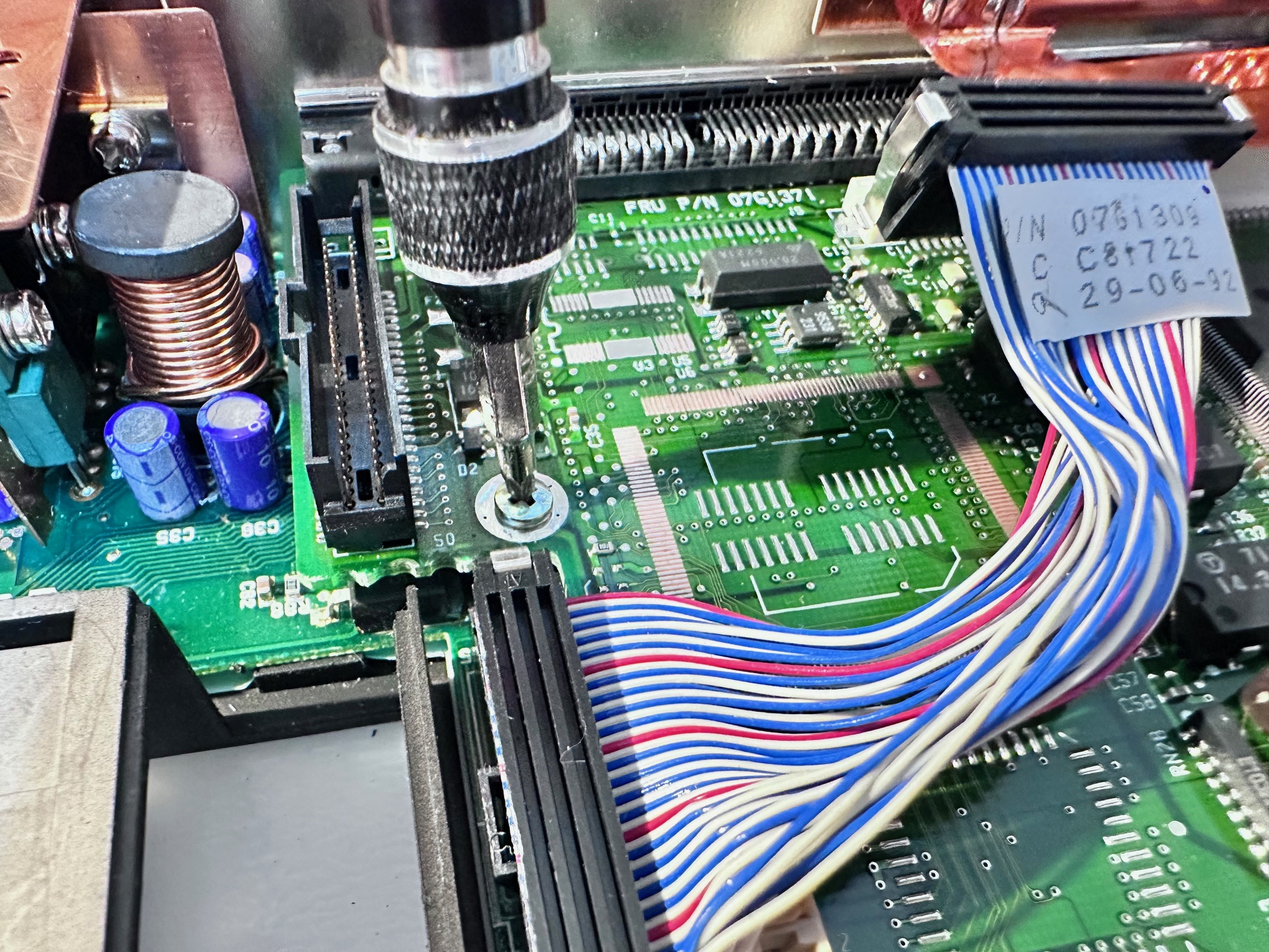
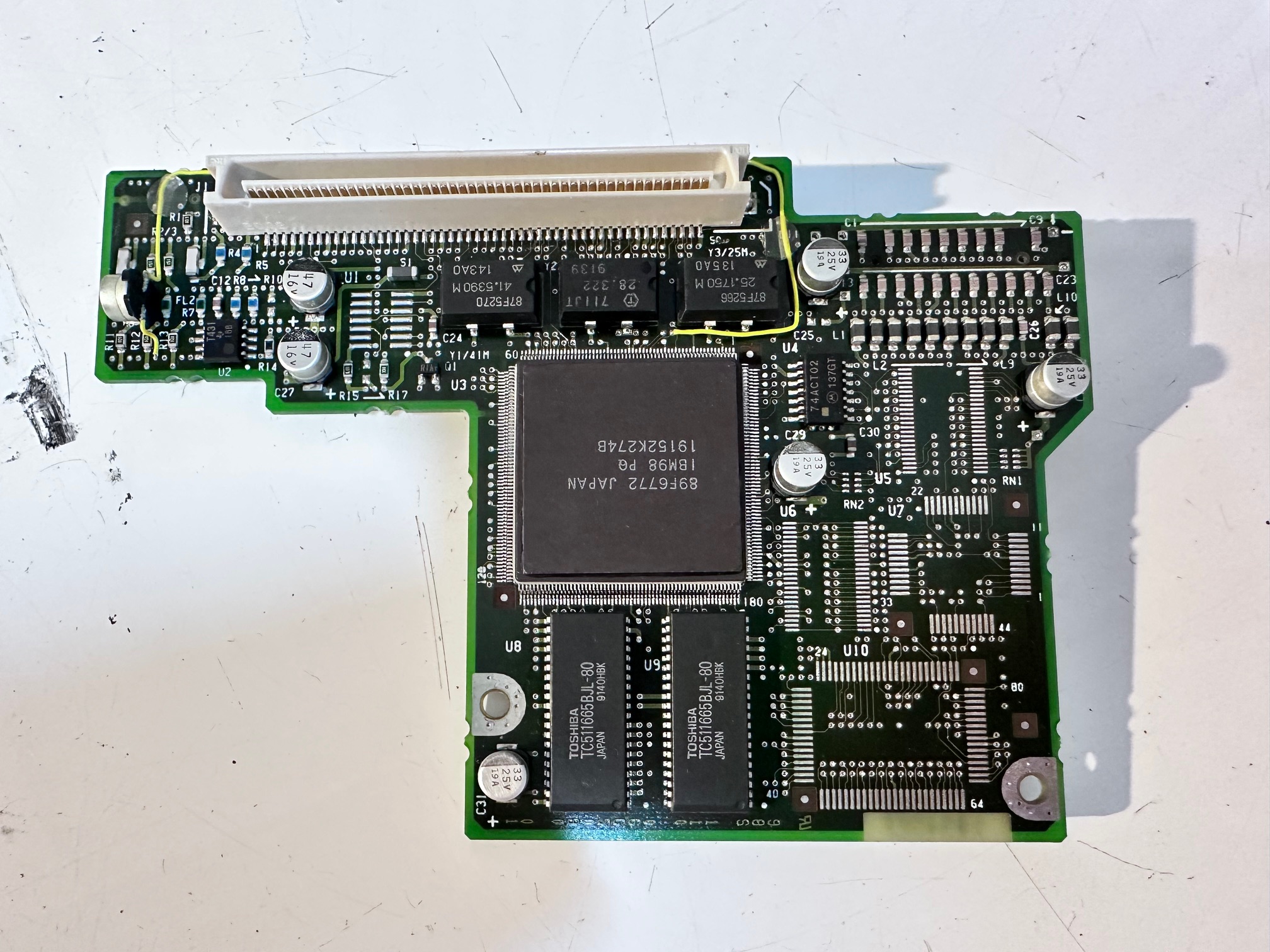
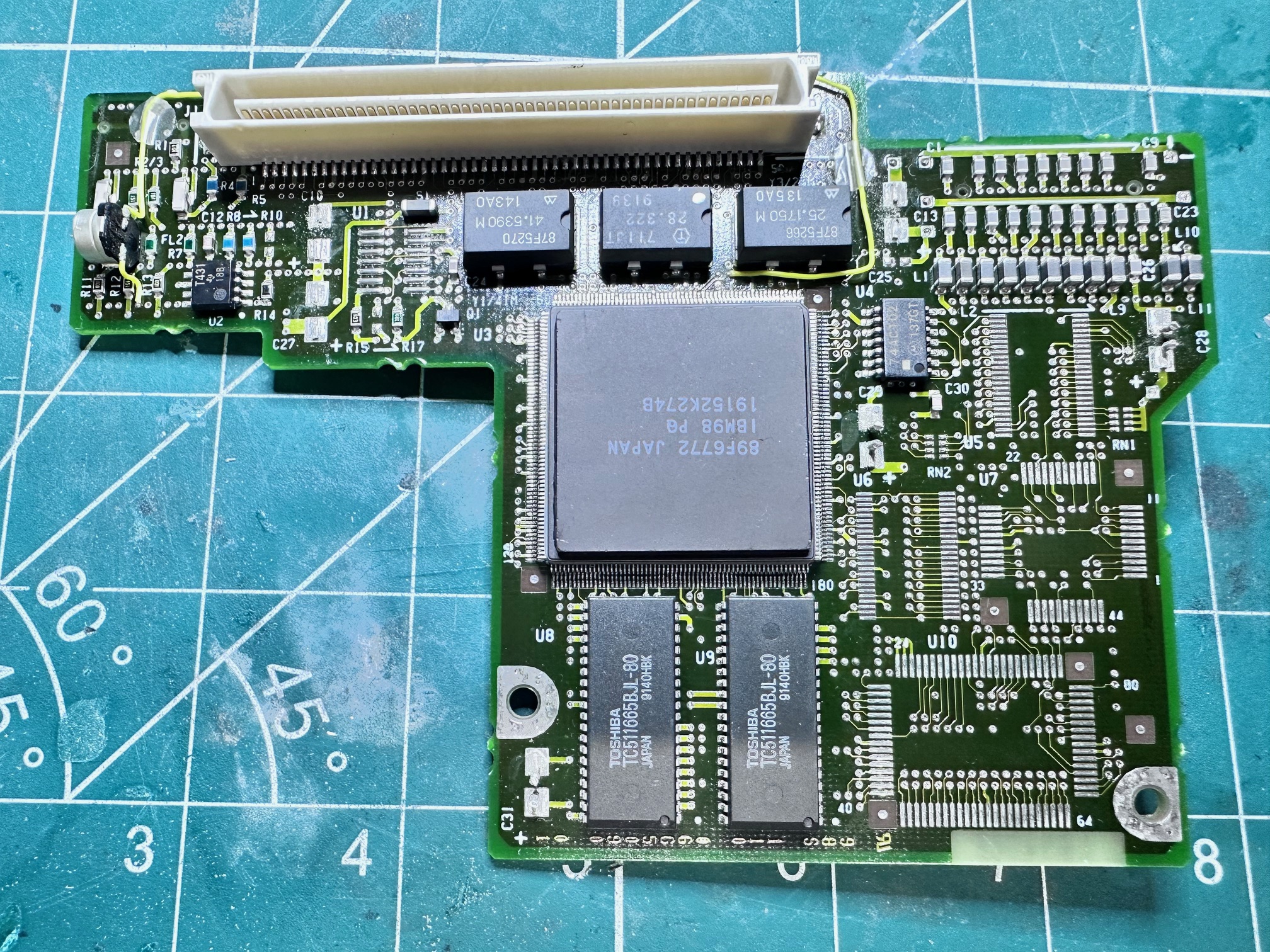
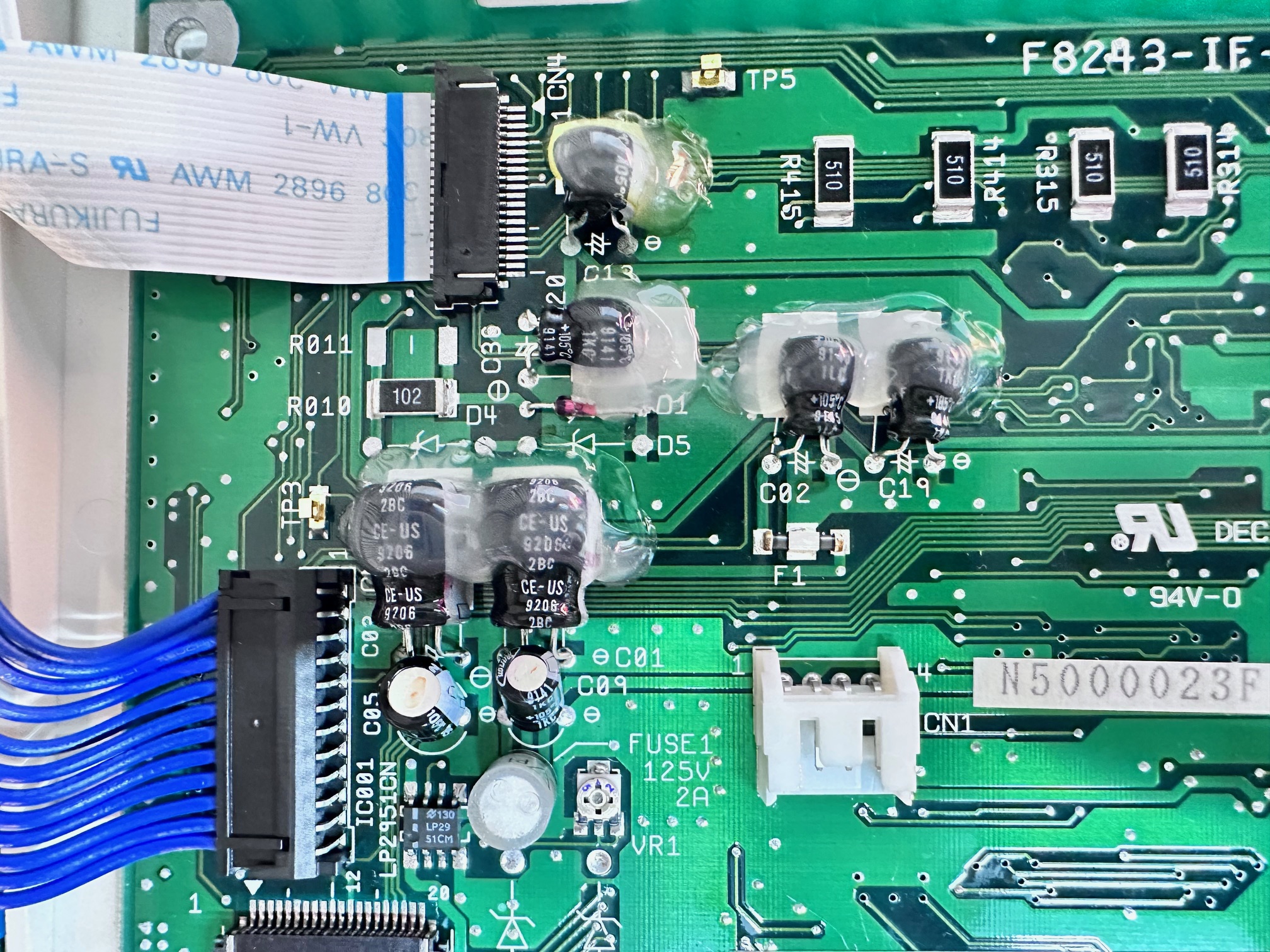
And the third board (working from the base up, is this board, which I think is related to CPU and some memory for maybe video or cache or something. This has 7 surface-mounted capacitors on it, and all of them leak and have failed. The one on the right is weirdly mounted on it's side....
Before removal:
With the caps removed:
This is the board cleaned:

And finally with a sprinkling of tanalum and polymer solid state capacitors:

This is the weird single one on it's side:

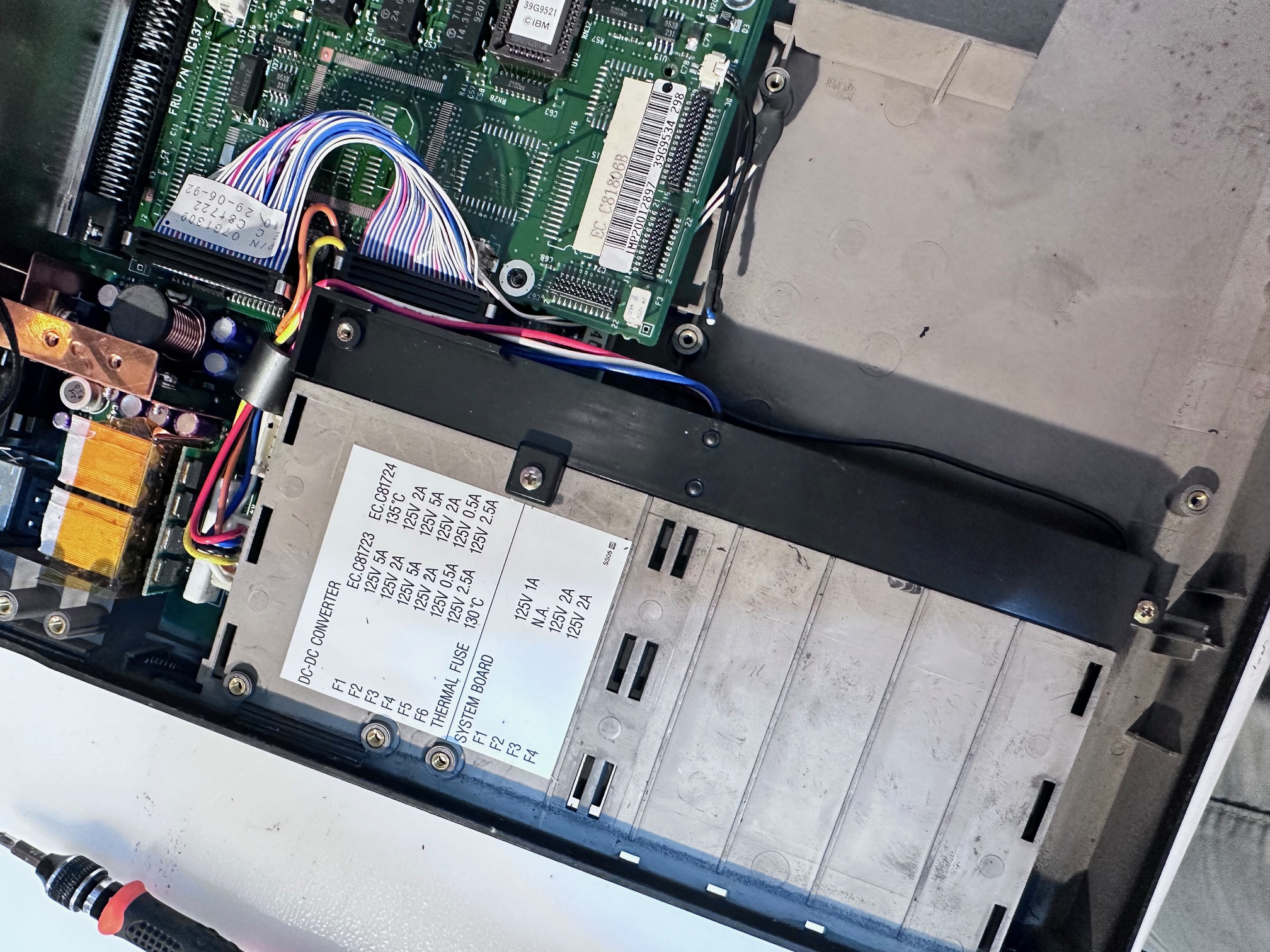
The next board is hidden underneath a large metal bracket at the far back of the CL57's base. It does look and feel associated to power, so I'm calling this the second of the two power boards. It just has 4 through-hole capacitors, all 15uf:


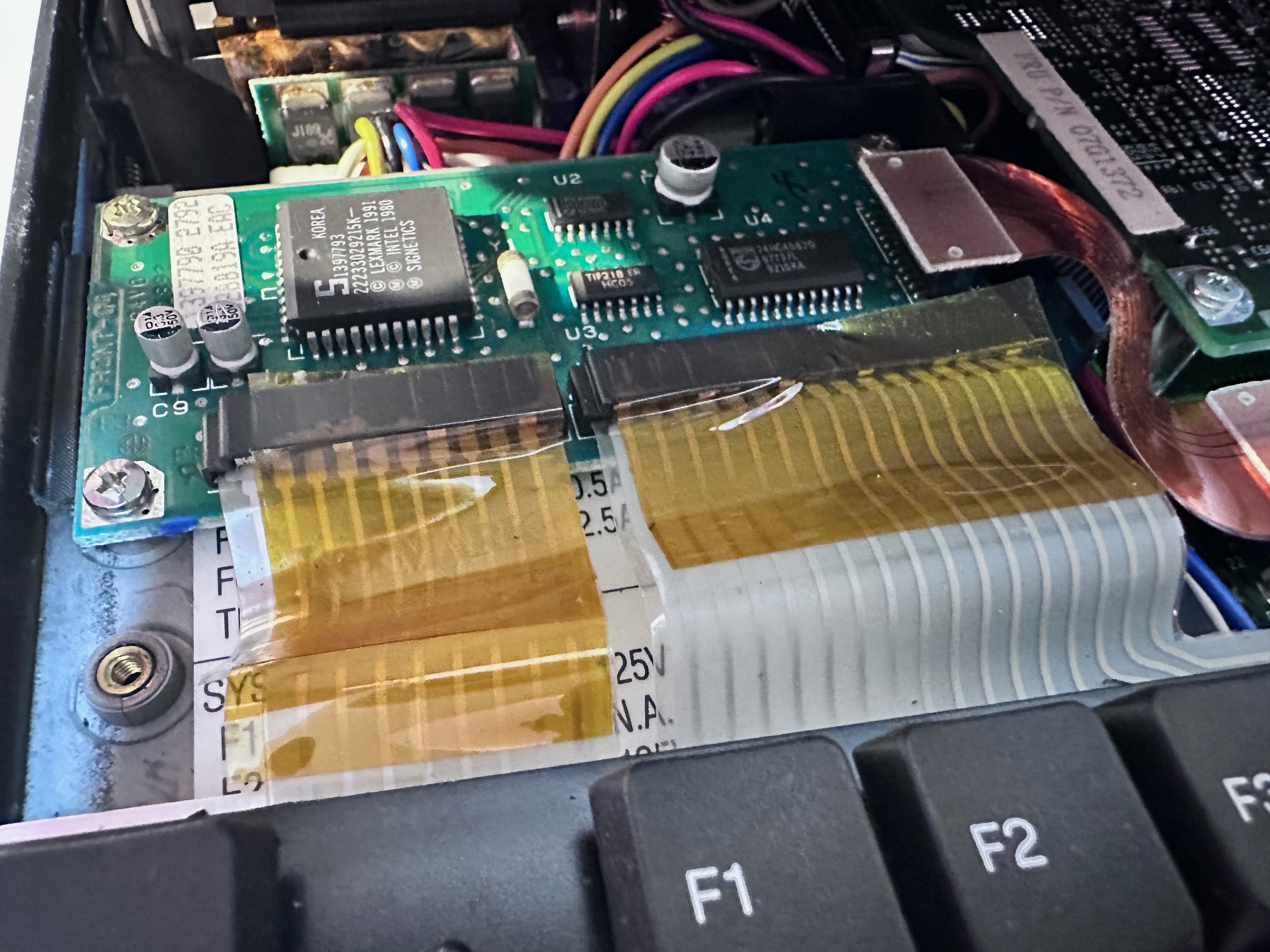
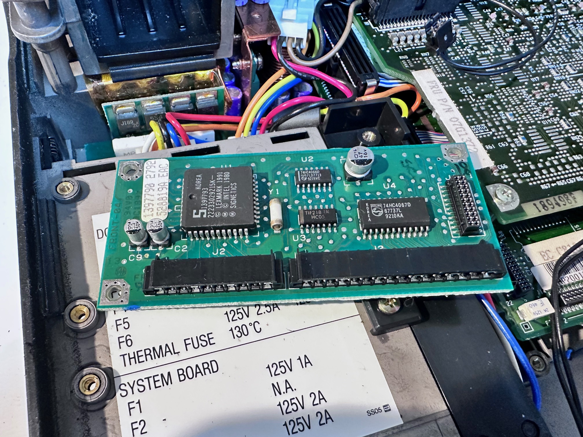
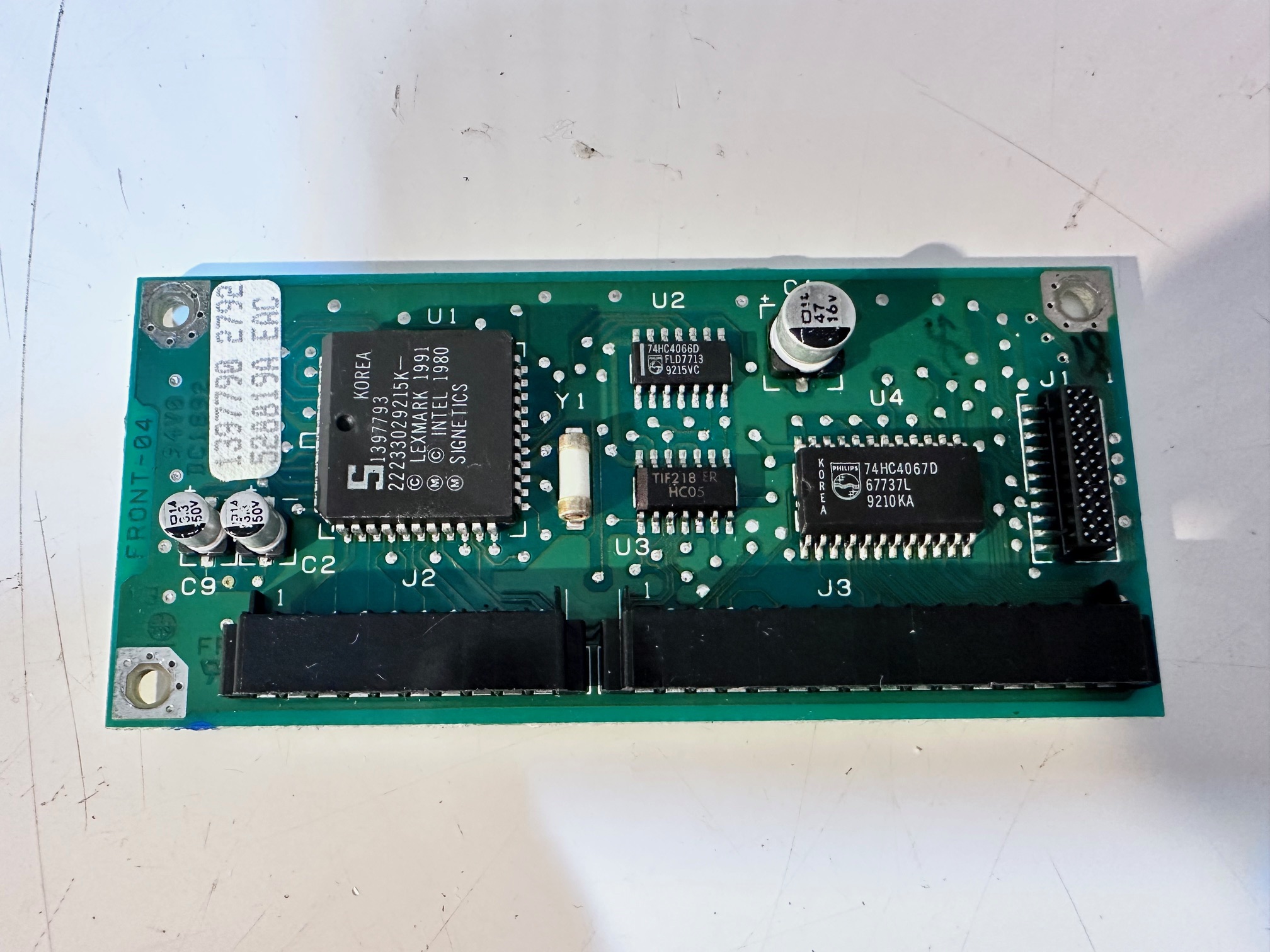
The final last board is the keyboard controller. This is also slightly unusual in that it's not really attached to anything. It takes a ribbon IN from the keyboard and another ribbon goes OUT to the keyboard. Nothing else attached! It has 3 x surface mounted capacitors, all leaking - 1 x 47uf and 2 x 3.3uf ones:


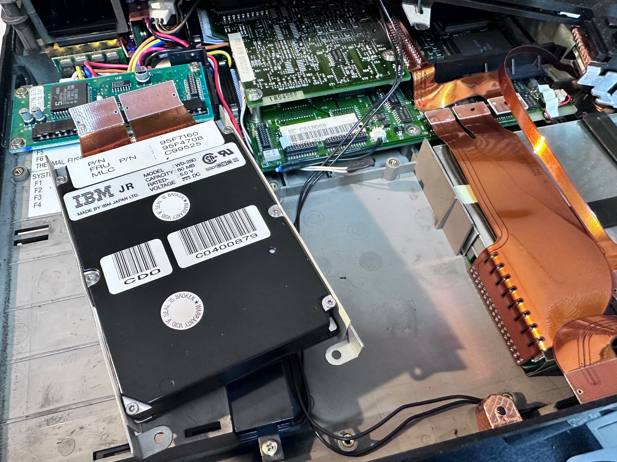
CL57 Hard Drive
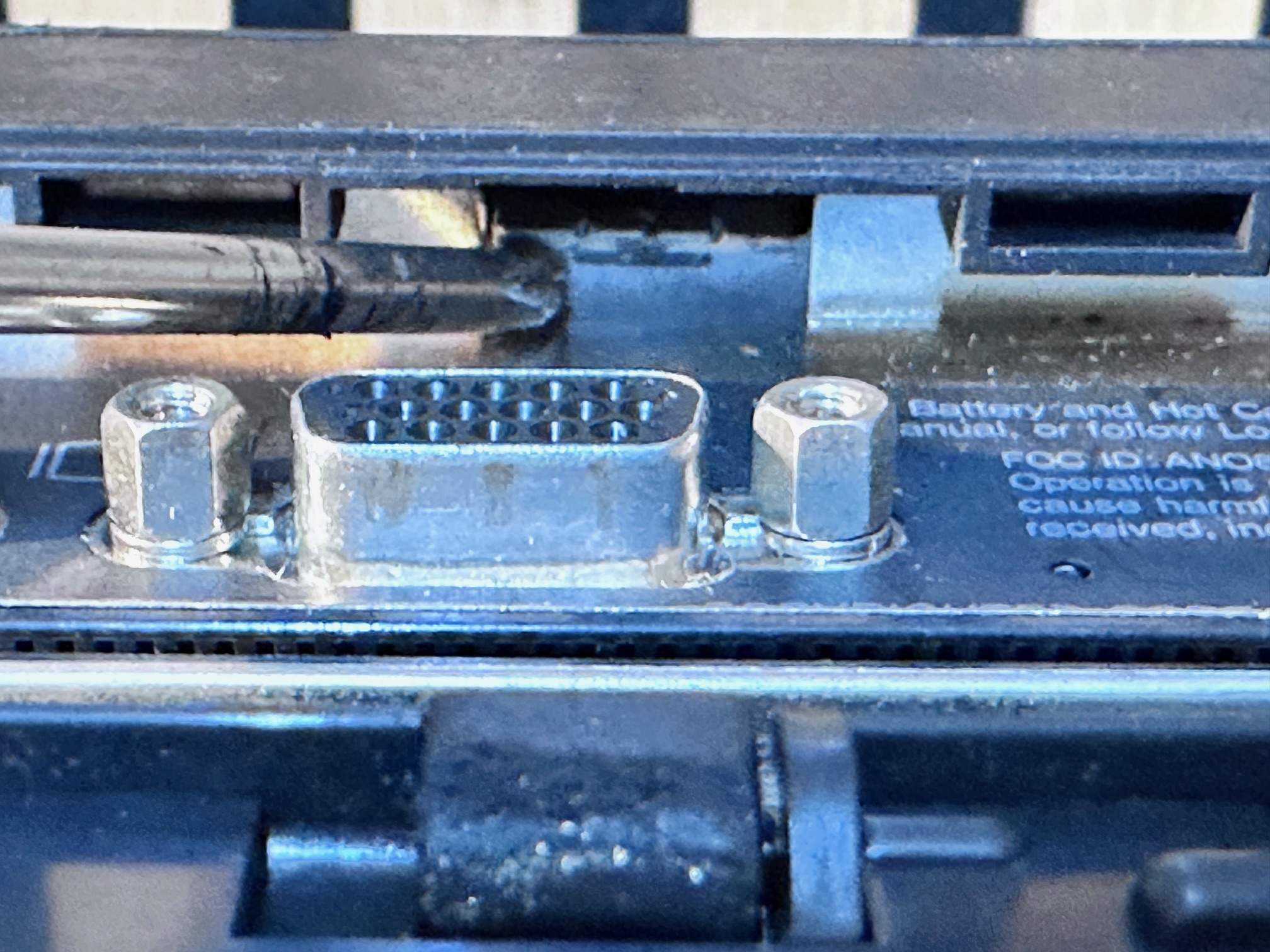
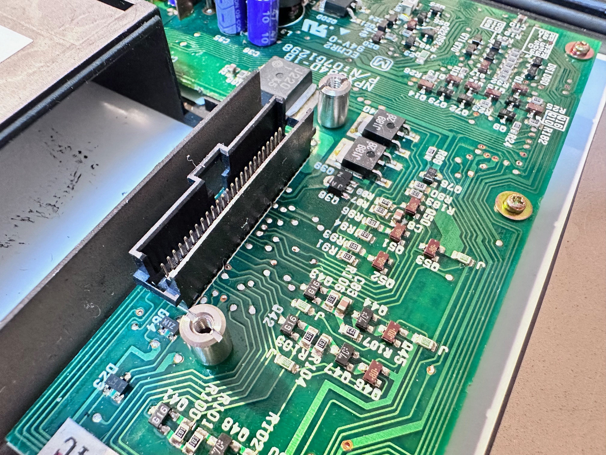
I've noticed that the ESDI hard drive for the CL57 (MCA architecture) is exactly the same connector as the PS/note N51. To my knowledge there isn't another IBM machine which shares this hard drive connector, mainly because most of the other notes are ISA, and the next-ish machine in the series of portables is the C52/Thinkpad700 which shares MCA architecture with the CL57 and N51 but it has hot-swap hard drives which have their own unique interface:


CL57 TFT Panel
Here is another couple of shots of the back of the TFT panel.

Finally, 'for fun' this is a list of the screws that came out and in the order they came out in!

Teardown Footnotes
There are a few things I noticed when tearing down a few CL57 machines:
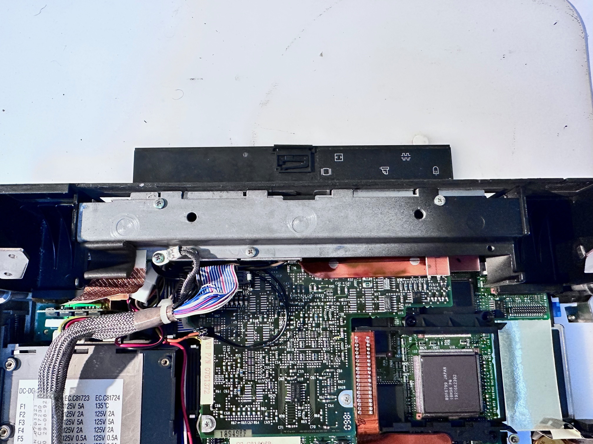
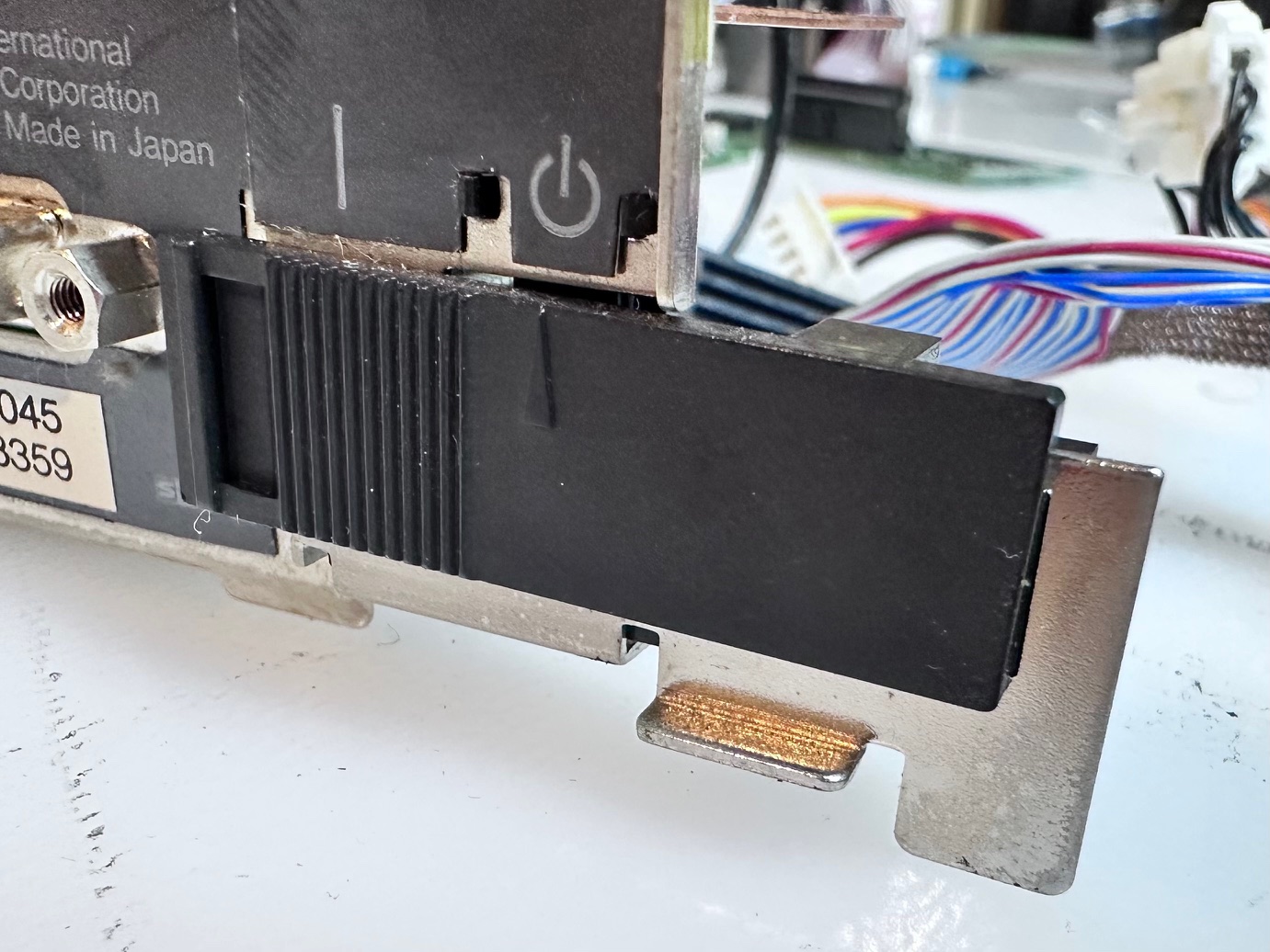
Hidden Power Switch
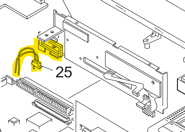
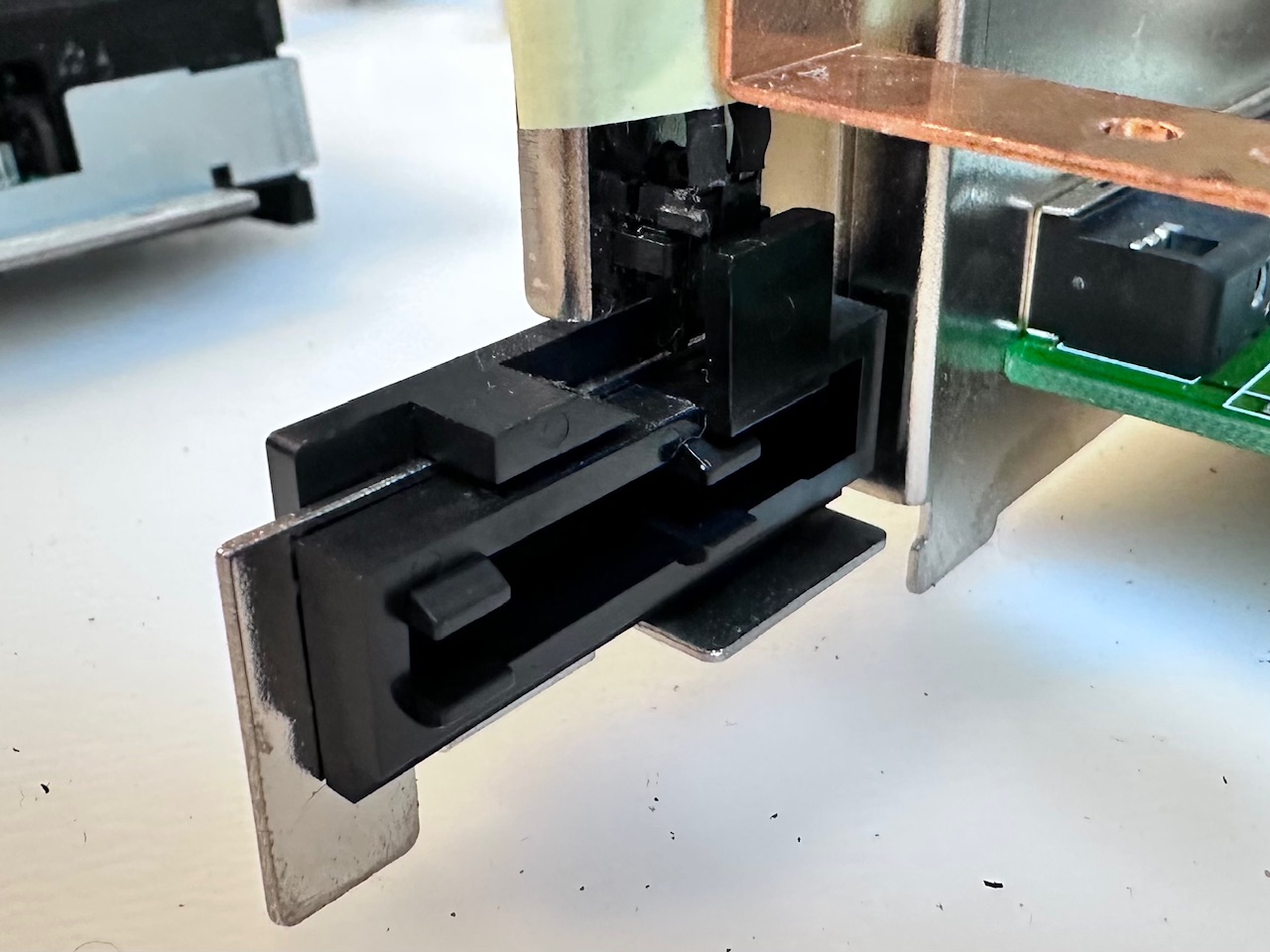
At the rear of the machine is a semi-hidden sliding, microswitched power switch used by the dock. It can easily be slid to the 'wrong' side meaning the machine will not power up - it will just blink some battery lights at you. Here is that switch shown in the HMM:
And here it is in the flesh:
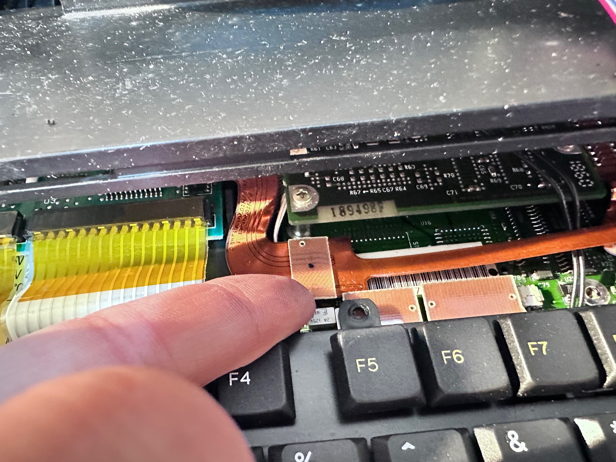
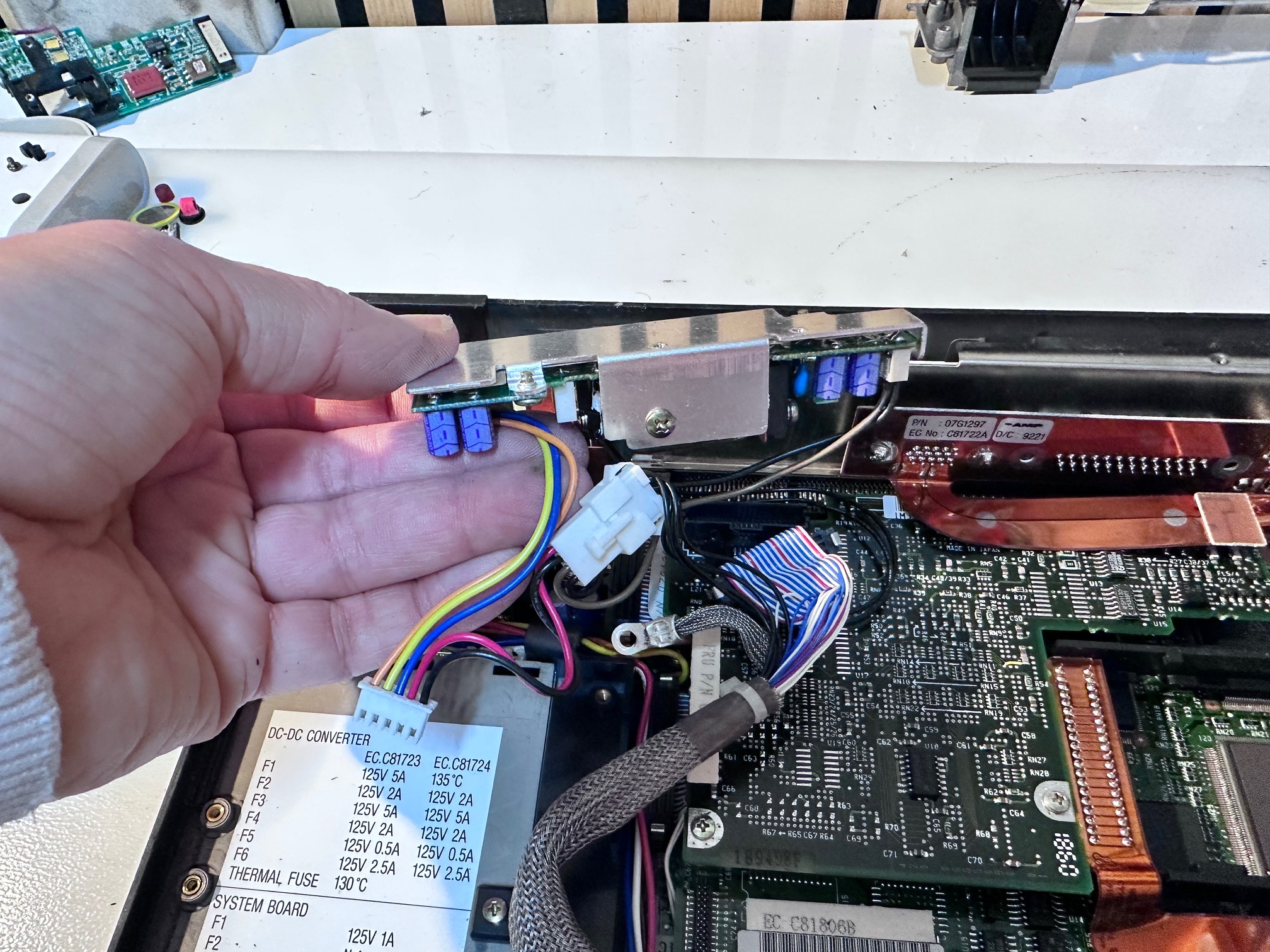
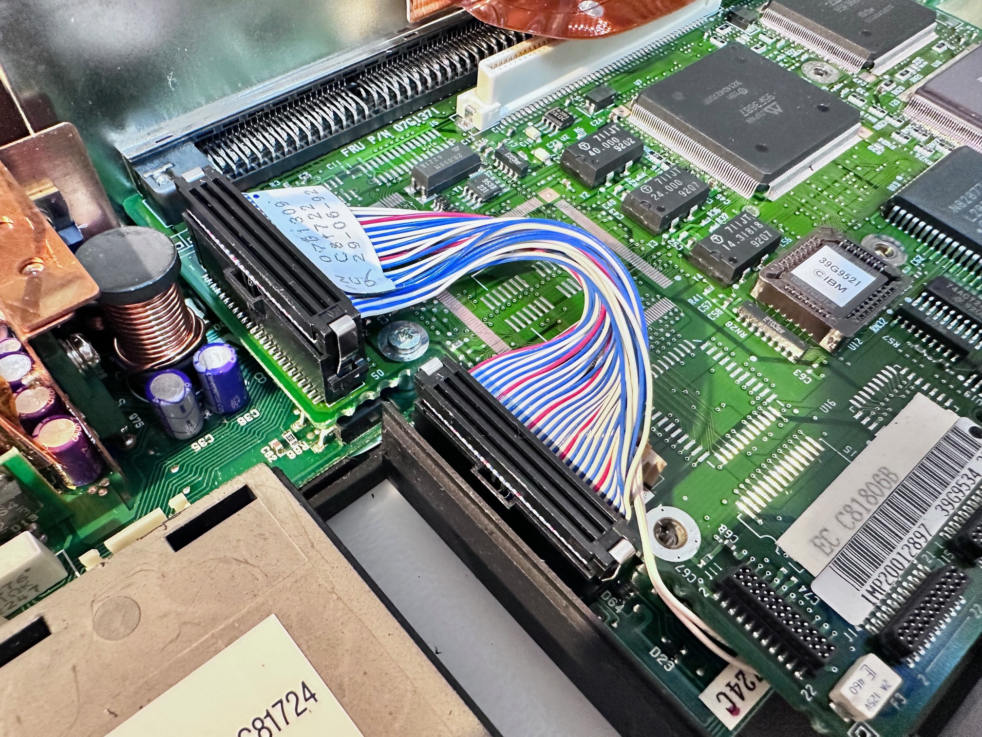
Voltage Regulator Cable
There is a cable inside going from the main power board at the back of the machine, behind the power connector and it has a connector to another board, which is sometimes present and sometimes not present. The HMM says this cable is not necessary and eliminated on some versions of the CL57:
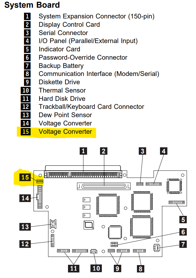
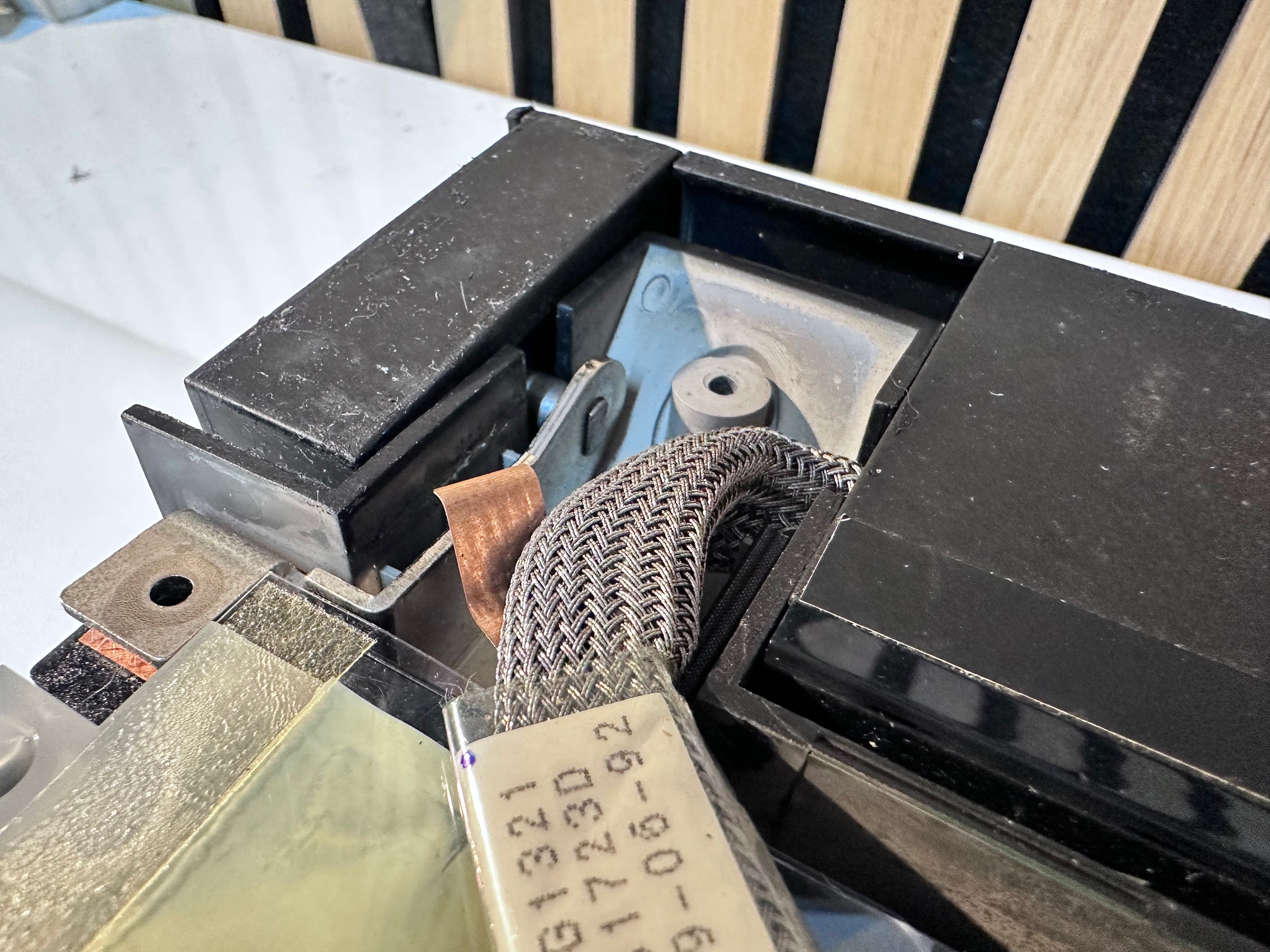
Here is that cable present on one machine:
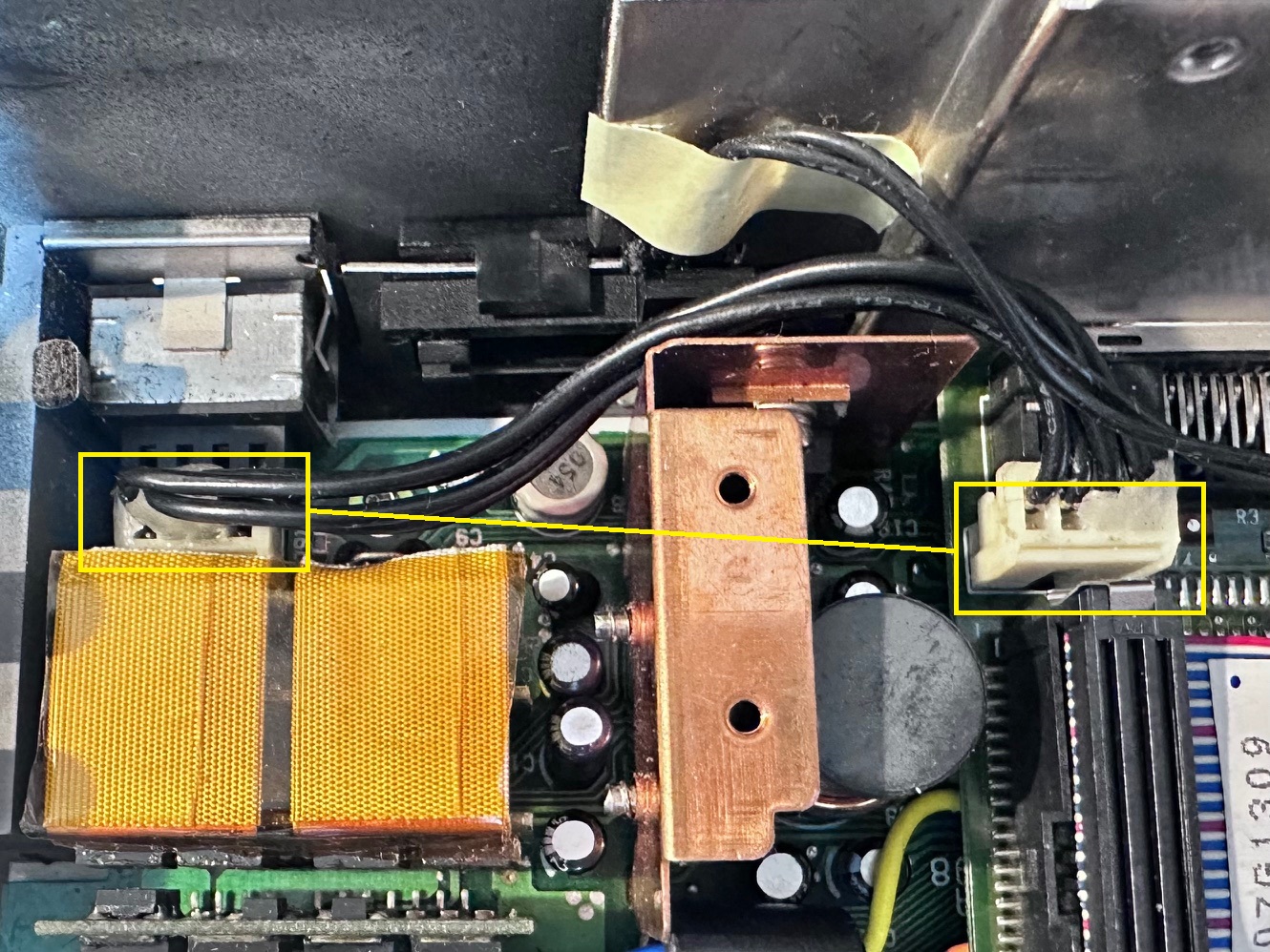
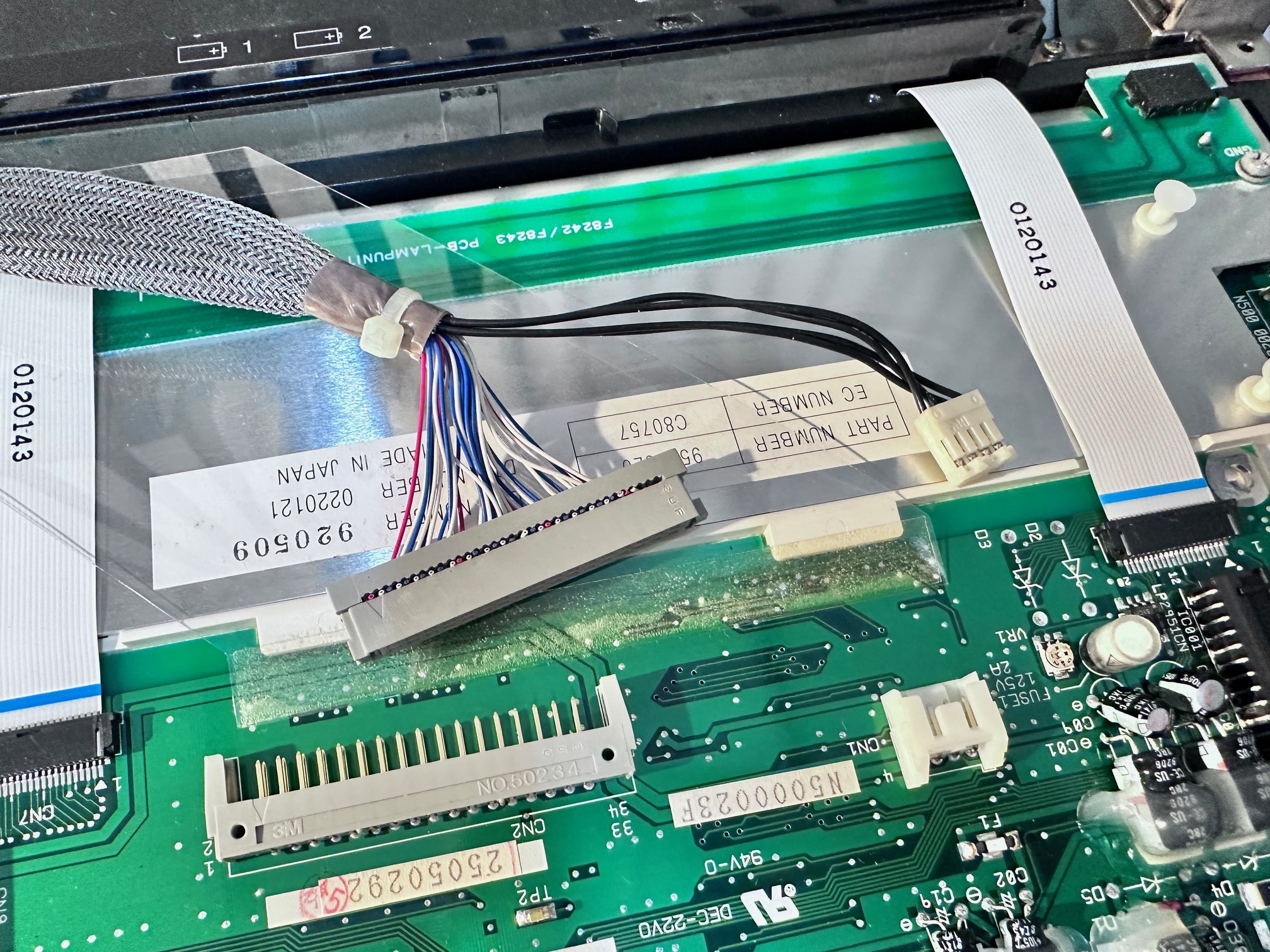
And here is it not present, which includes the right-hand connector being missing:
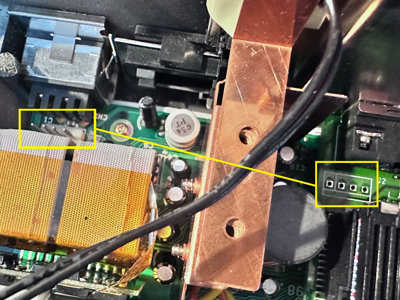
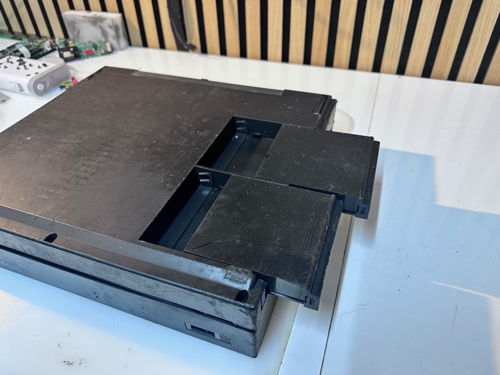
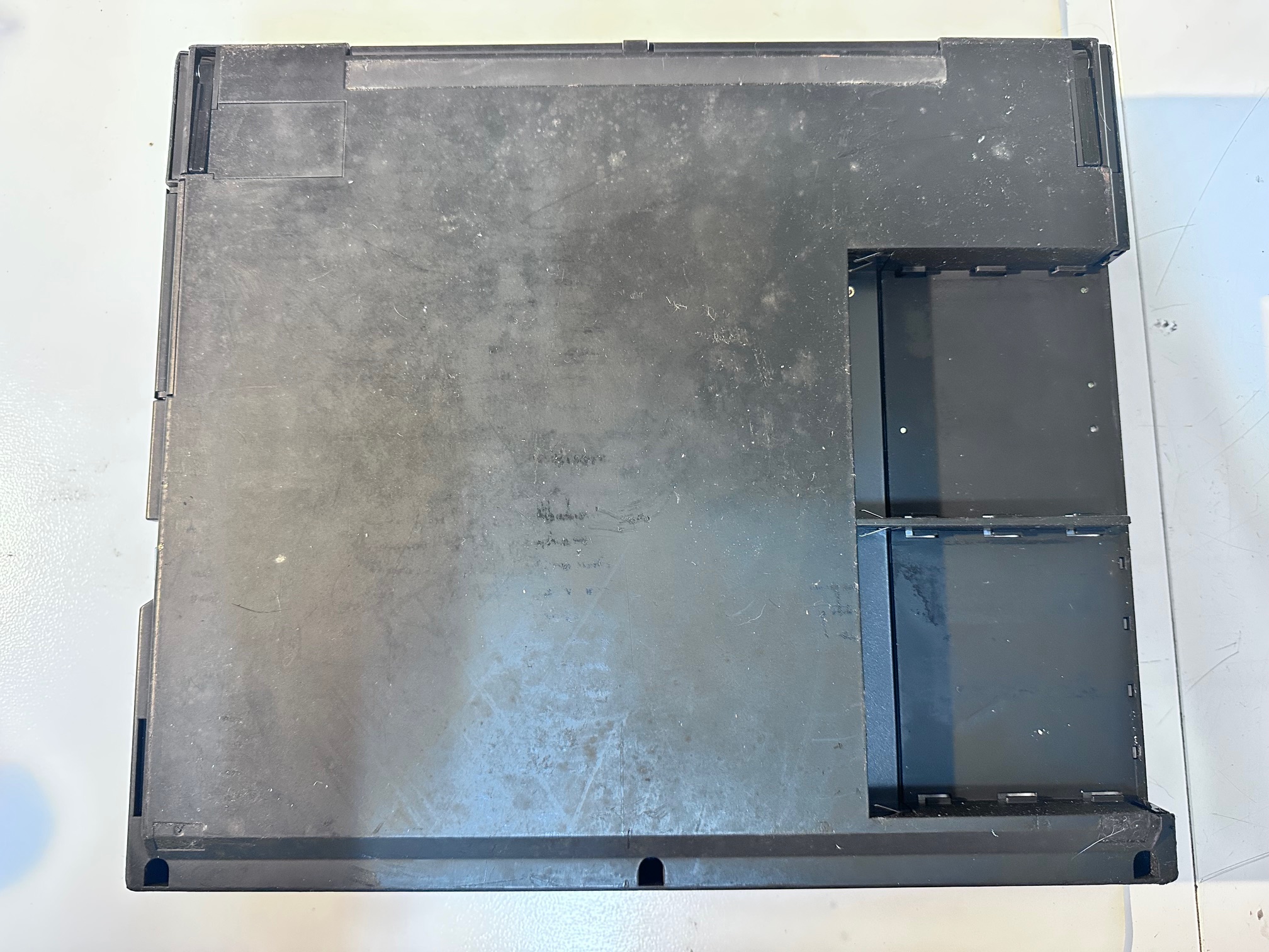
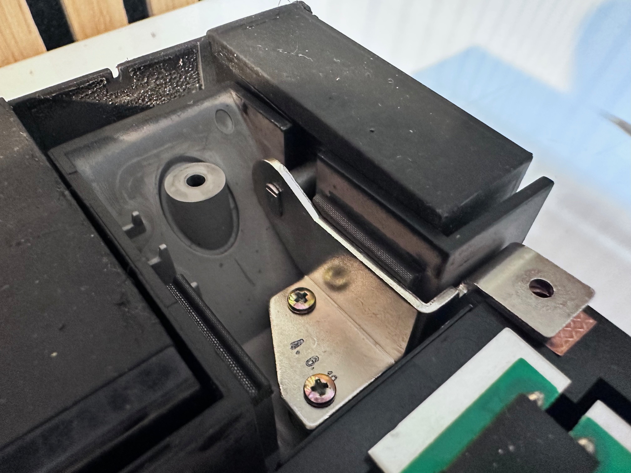
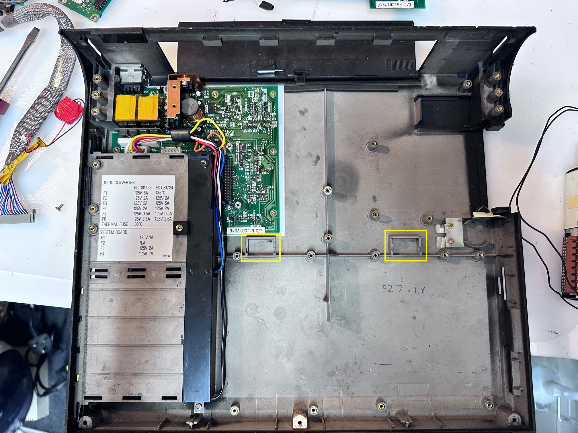
Odd Base Holes
Inside the base of one machine was two rectangle holes with plastic covers. I'm guessing for some kind of dock.... On the other, no holes:
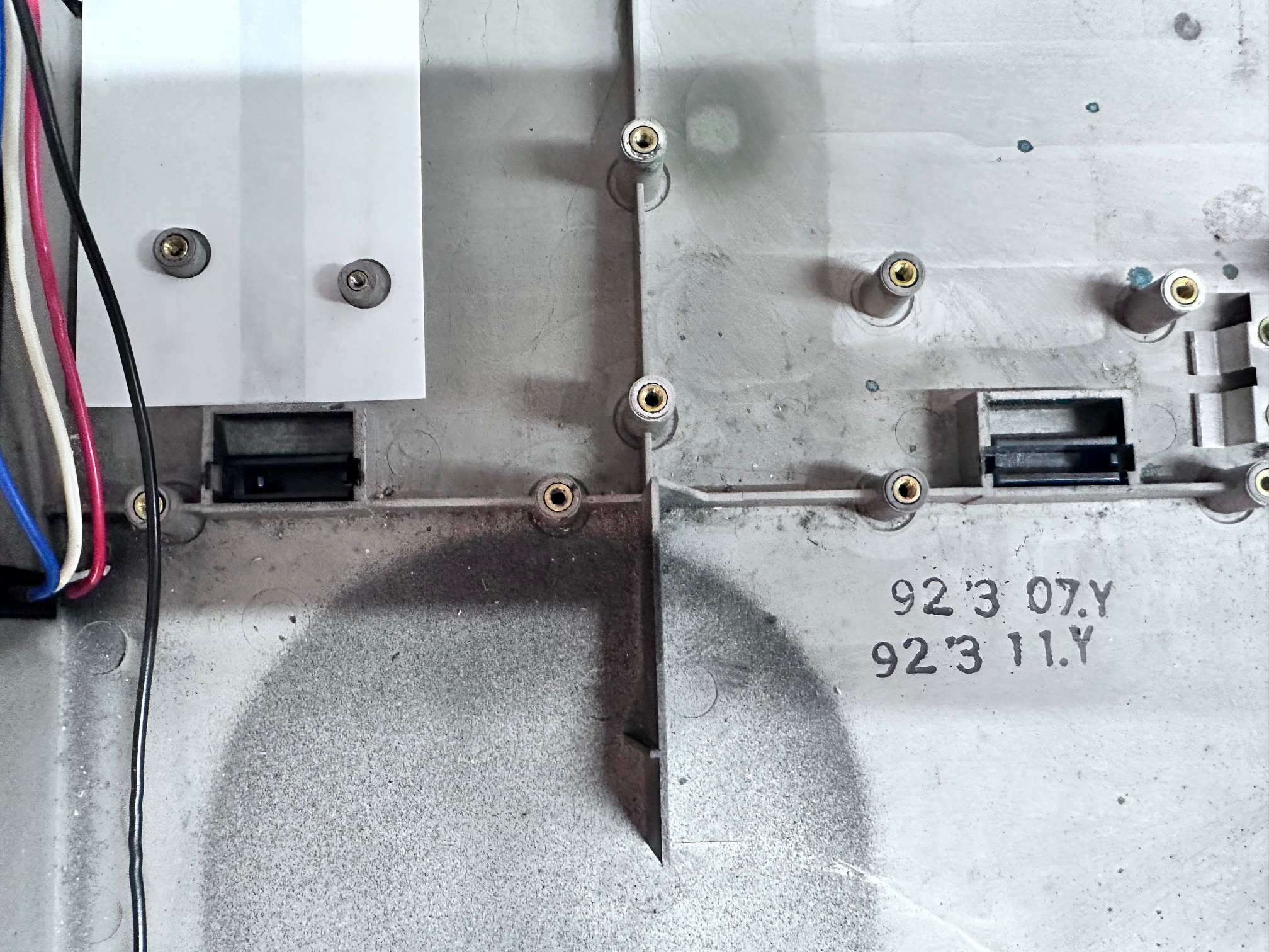
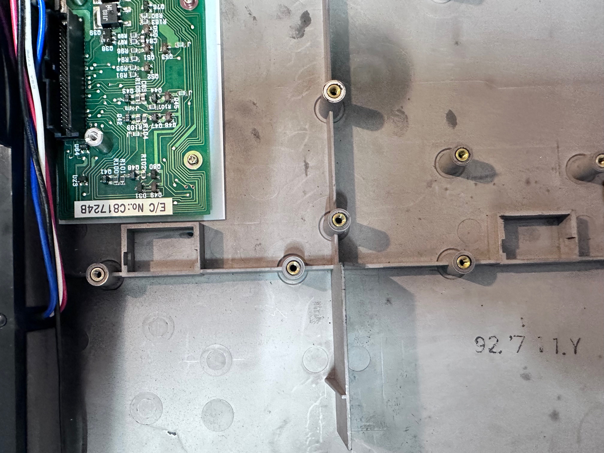
And.... no holes:
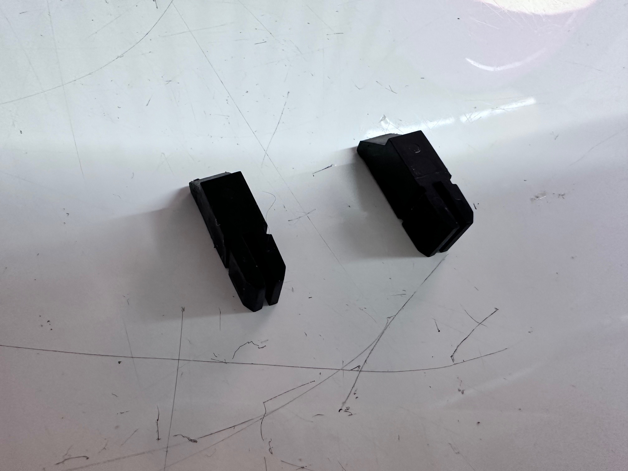
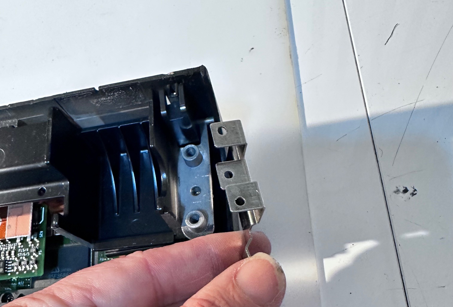
Missing Bracket
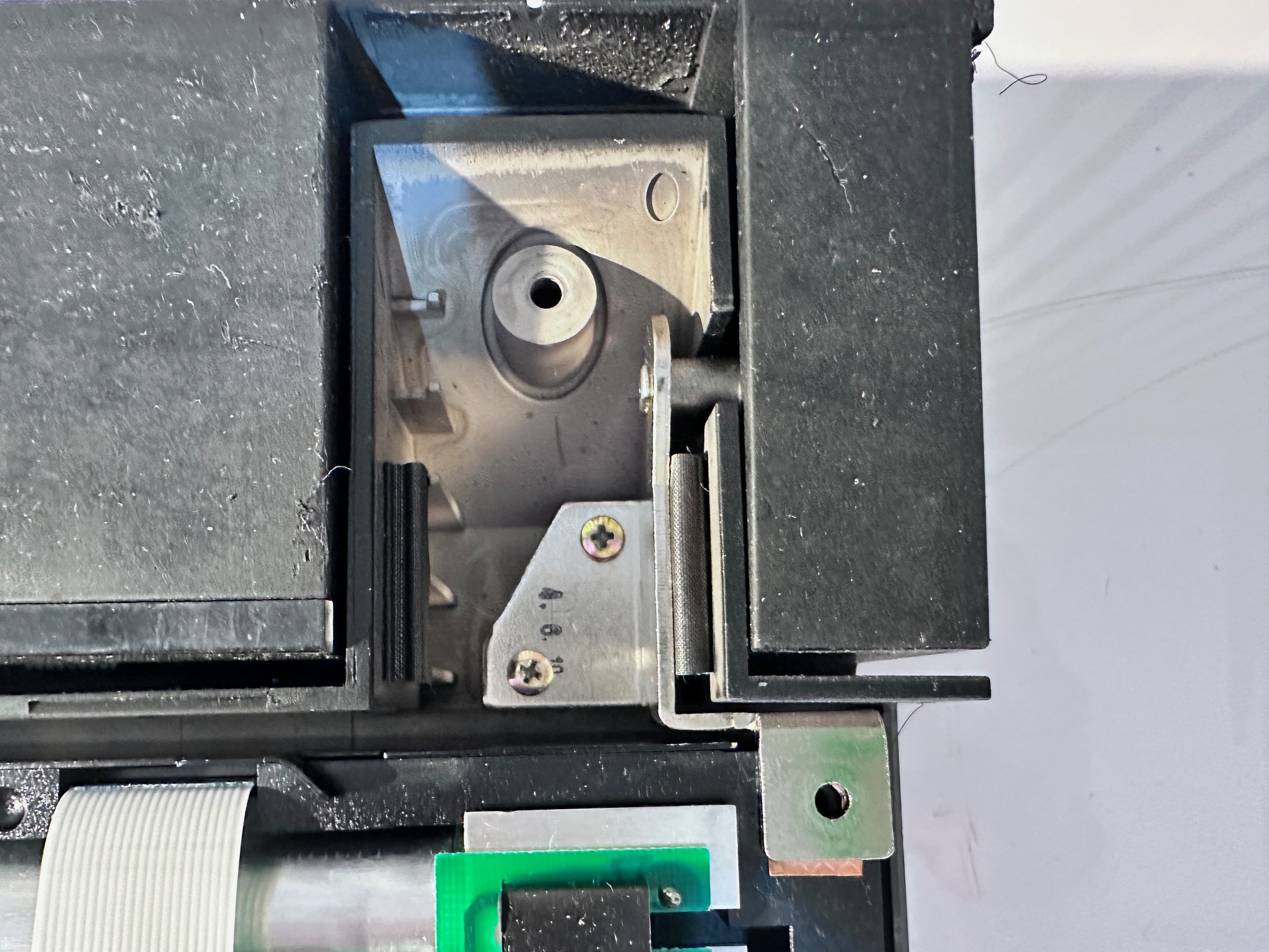
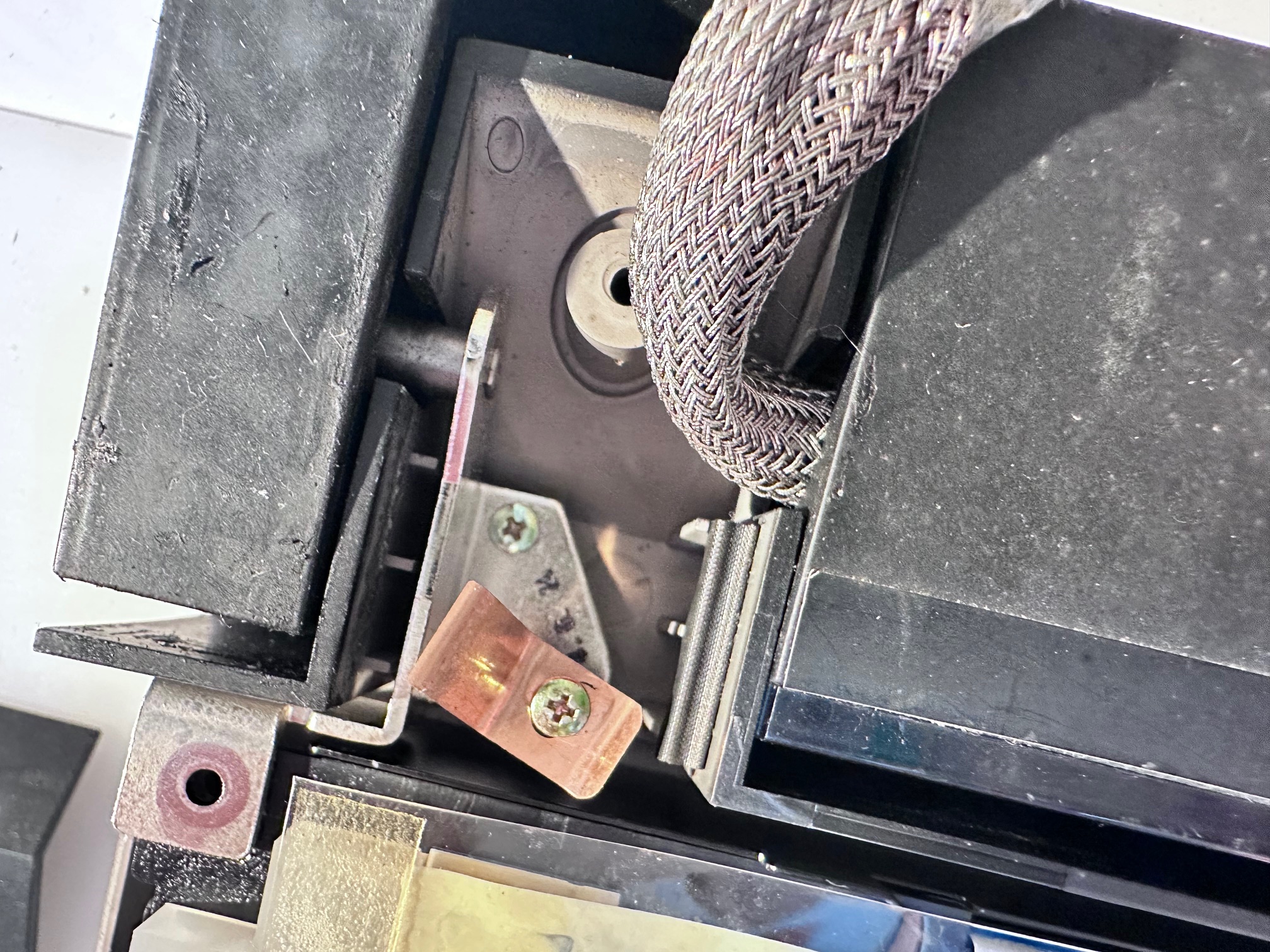
On both machines I did a teardown to, both were missing the left bracket shown here:

I really don't know if the bracket has been lost on both machines as they both looked like someone had been inside at some point in the past, but both were missing it.