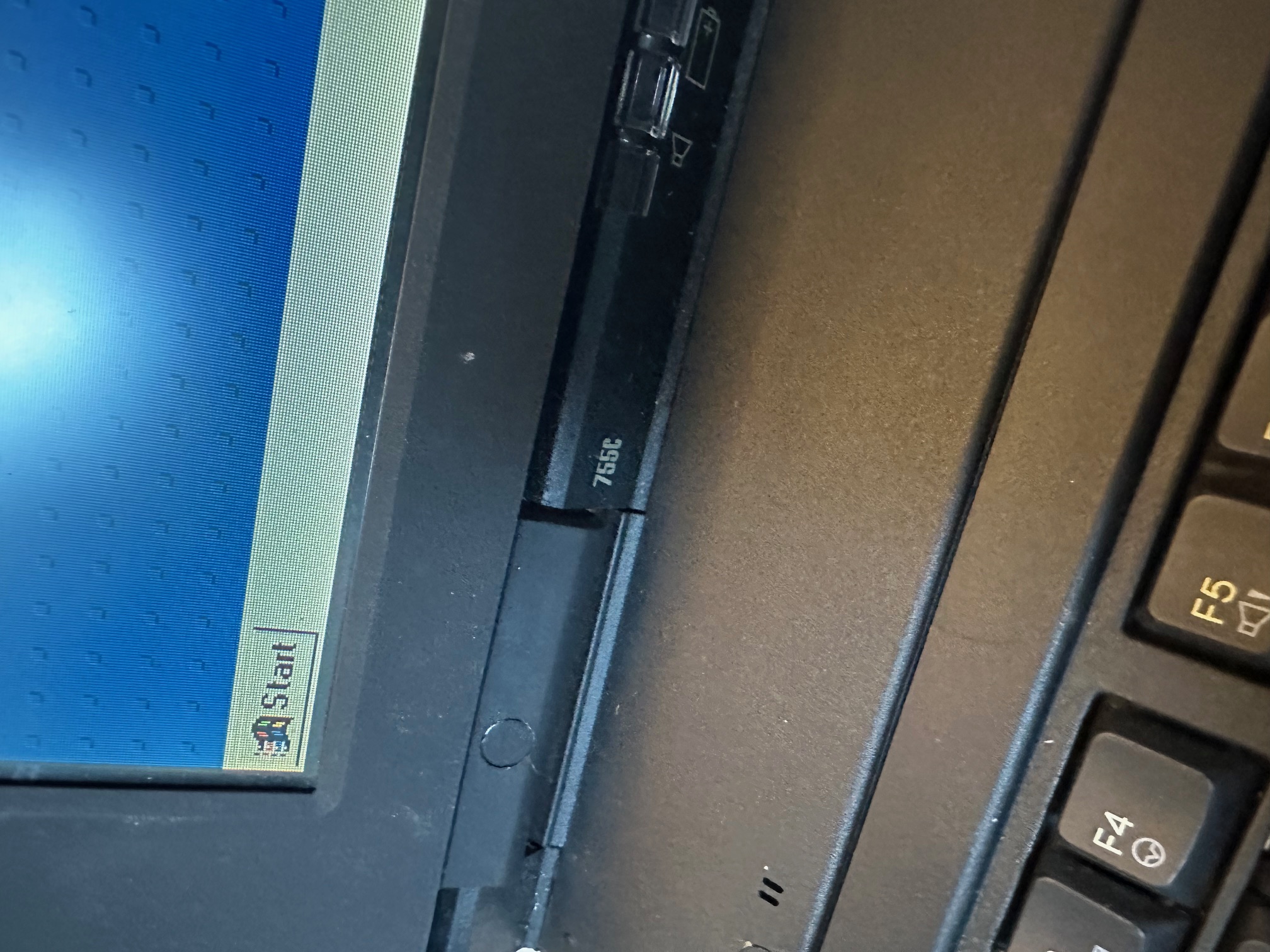
I acquired a foreign (to the UK) IBM Thinkpad 755c. Here are some notes I made considering I spent a few hours today.

The 755C and 755Cs is closer in architecture to the 750-series machines than the later variants of the 755 range, such as the 755CE/CX. You would often assume any 755 has parts interchangable with the other 755 machines but this isn't true. There is not much you can easily swap between the early and late 755 machines.
The most obvious visible differences between the early and later 755 range are:
- The early 755 machines have a seperate LED indicator cover, as opposed to the later ones which combine the big flat plastic cover above the hinges with the LED indicator cover.
- The early 755 machines do not have an analogue roller volume control above the keyboard (and have a much smaller speaker inside).
- The early 755 machines do not have a detachable internal RAM daughterboard, underneath the main motherboard, like the later 755 models have.
As covered in a seperate article you can use some parts of the 750 in the early 755 machines - such as the lid with display and it's ribbons is one big switchable part, although many keen eyes would easily spot the later 755 LCD in a 750 machine. The 750's plastic base does not have a removable piece of plastic above the two external audio ports, unlike the 755.
You can also use the plastic base from the 360 on the 755, but it does not have the rubberised coating (which does mean it ages far better) and of course the model number on the base is 2620 rather than the 755's 9545 model designation.
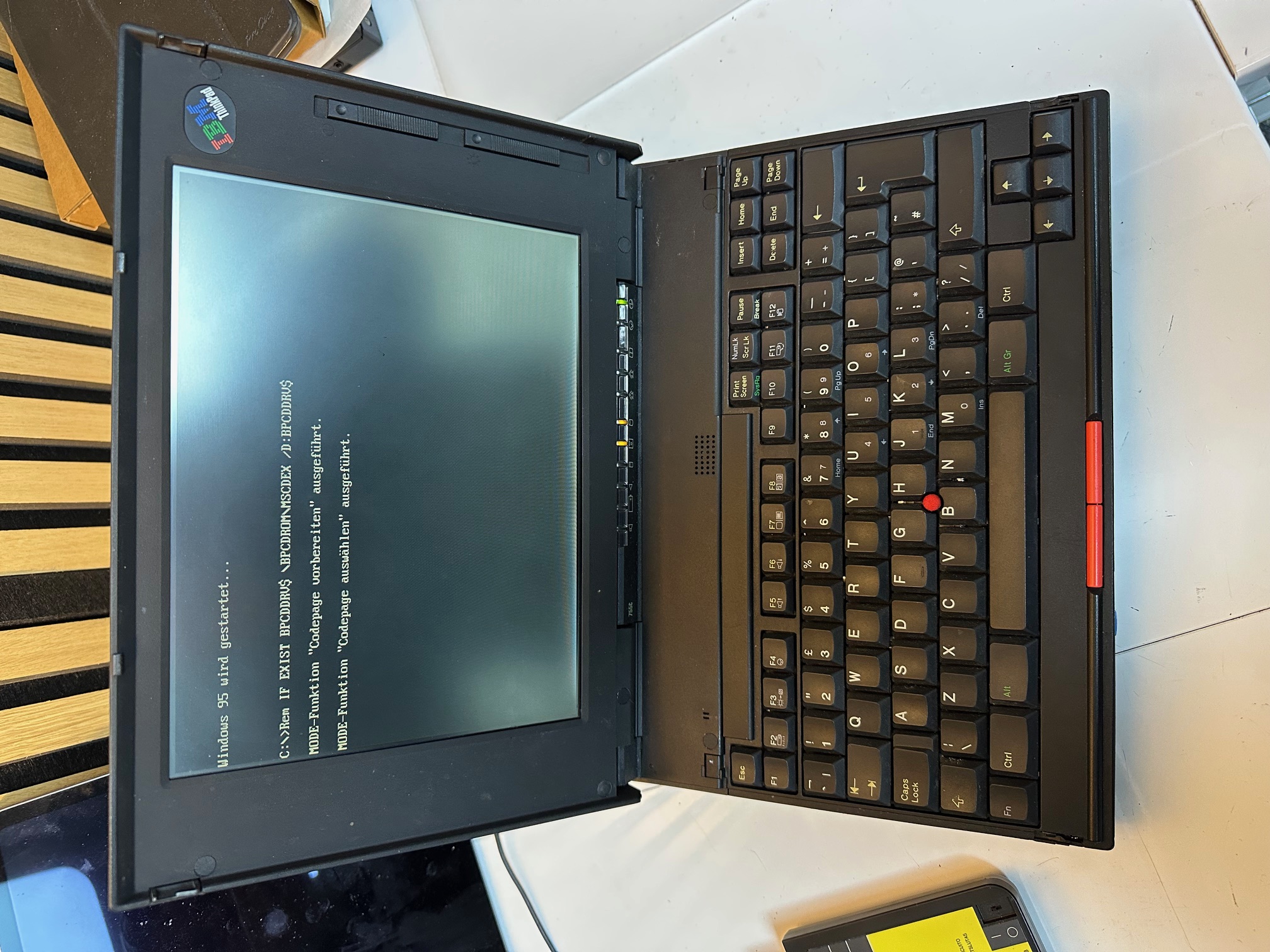
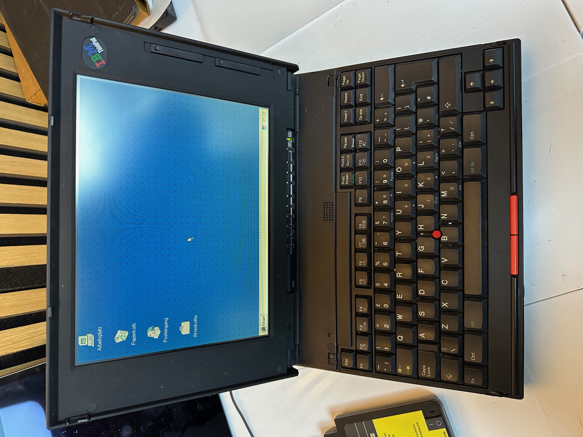
My first machine
The machine was in good working order, once the battery was removed. With the main battery fitted, the status LEDs just flashed you when you pushed the power switch and all went out. This is a common issue with drained Ni-Mh batteries.
Also the CMOS battery was dead, so I used the old one's wiring to swap in a new 2032, to save having to set the time every single cold boot.
It had the base/built-in RAM only, which was 4Mb, so I found an older, parity IC-DRAM card to go in, which was 16Mb, giving a total of 20Mb. Much faster W95.
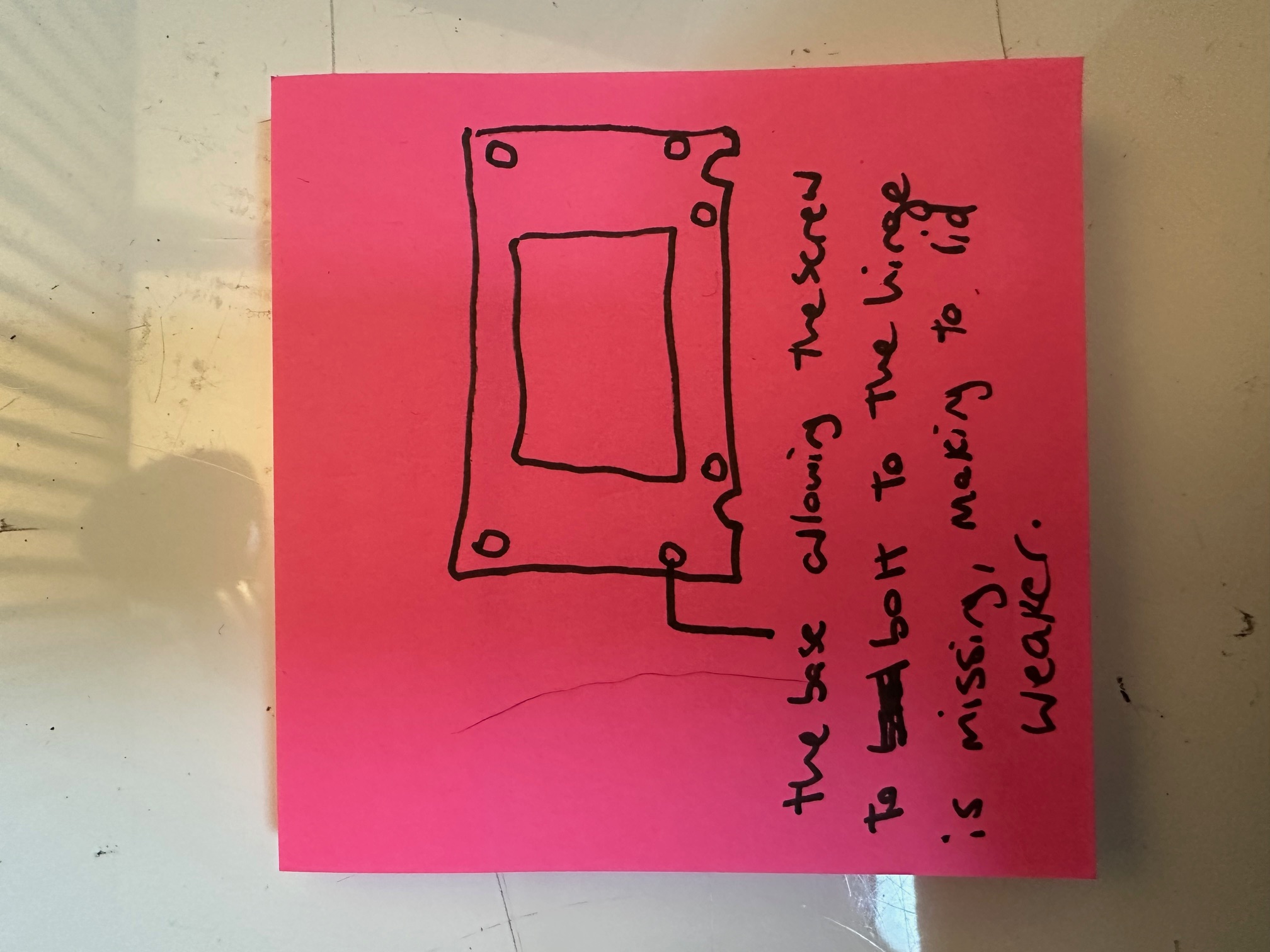
The main issue, which remains is the lid. The hinges are held tight by 3 different screws on each hinge - the middle one on each side screws directly into the lid which is seperate from the front LCD bezel and all the display electronics. Then the outer screw of each hinge passed all the way from the front LCD bezel, through the hinge to the lid and the inside screw the same (but along the bottom of the bezel). This means that when you lift the lid, those 2 inner and 2 outer screws passing front to back, through the hinge are doing a lot of the structural support heavy lifting.
I had two issues - on the left/bottom of my lid, the brass, threaded screw supports had come out of their circular bases in the lid. I superglued these back in position but failed to notice that on the LCD bezel, each of those 4 screw holes obviously has an inner, sunken ring for the screw to bolt-down onto, to secure it's tightness to the lid. The far left one has long since snapped off and gone, so after putting it all back together, whilst I have improved the integrity of my lid, by re-gluing the supports, I'm still down to 75% tightness because my front/left screw isn't bolted tight against anything in the bezel. This means that my left side of the lid is floppy and loose.
I have several 755CX lids and whilst I know the ribbon cables are different, I have not tried swapping the front LCD bezel around, which I may try next.
You could say this was disappointing but at least I know what to do next!
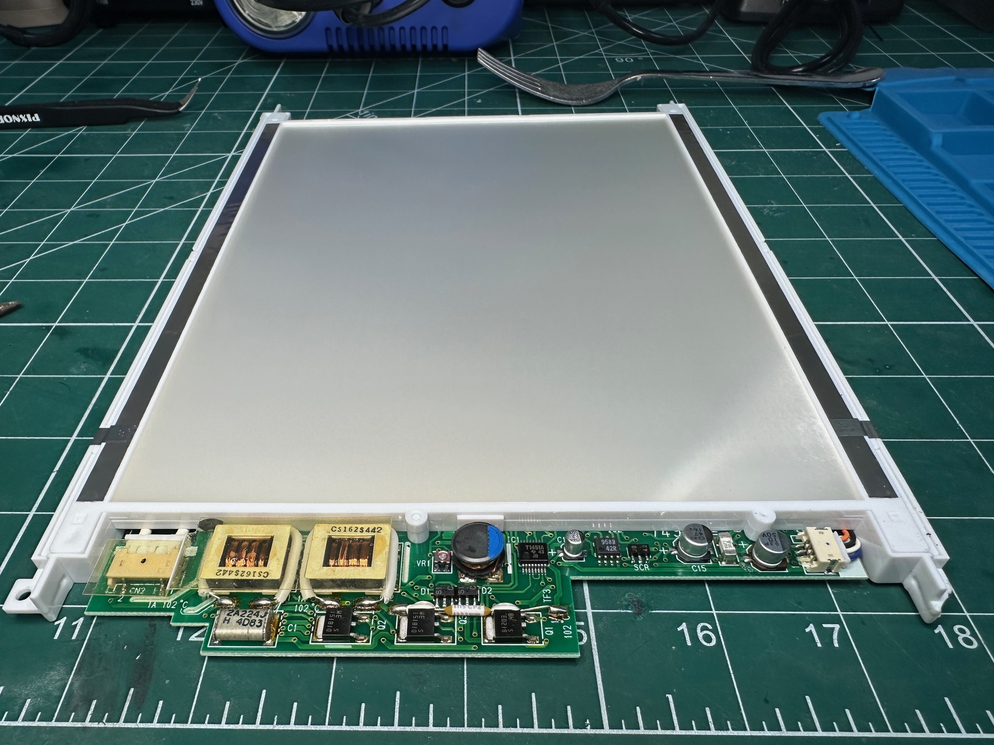
Whilst the lid was off, I investigated the capacitor situation within the LCD assembley. The 755c has 3 different PCBs within which each have their own capacitors.
This is the rear of the assembly, removed from the LCD bezel:
First we have the PCB which is attached to the large white backing and CCFL lighting which has 3 surface mounted caps. 2 of the 3 had leaked and had crustyness all around their bases. This is before:#
And this is after:
The small board which connects to the thin display ribbon has a single surface mounted electrolytic:
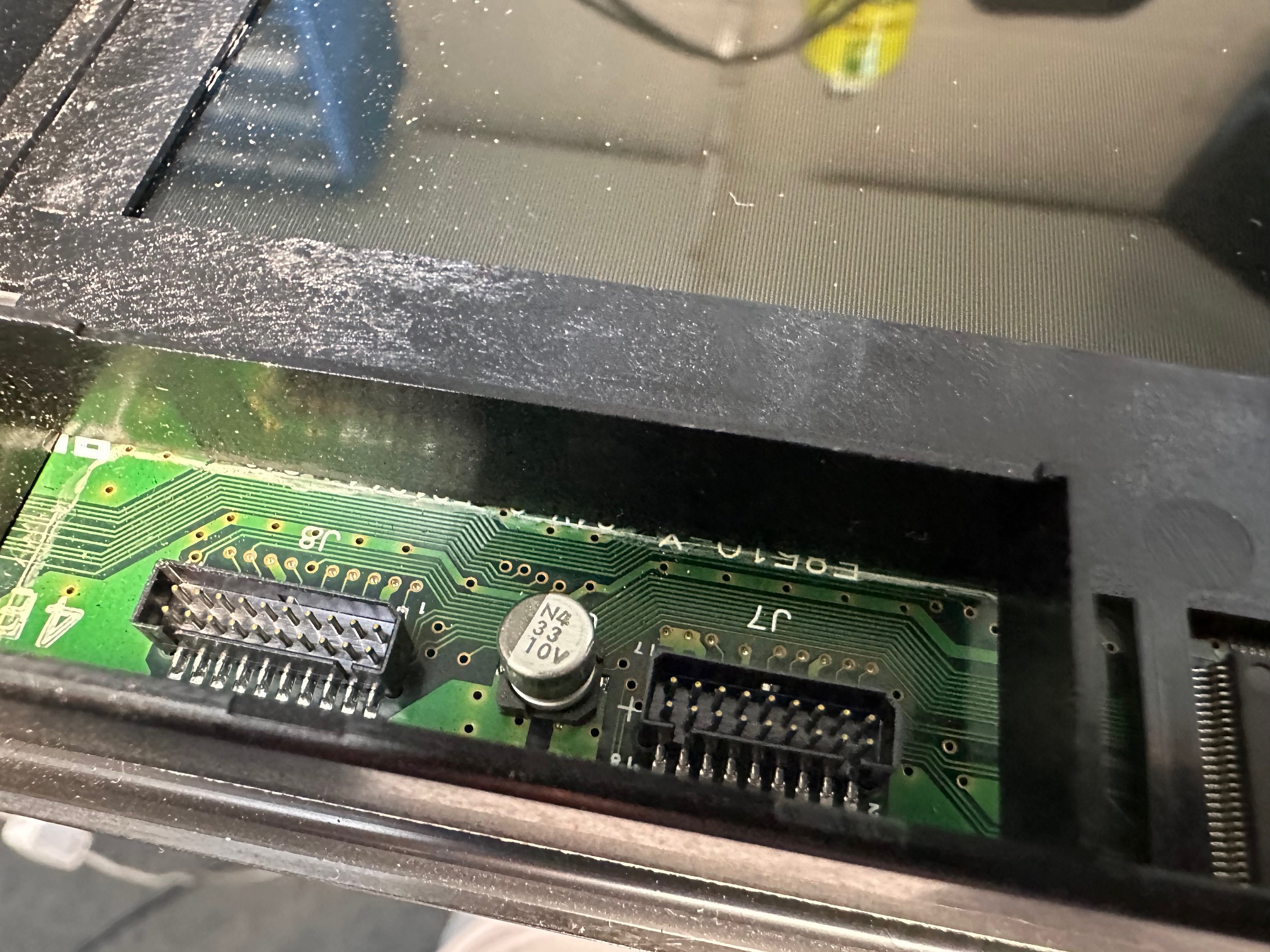
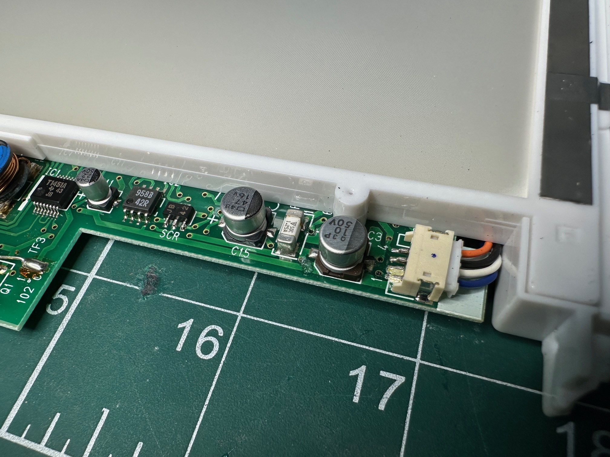
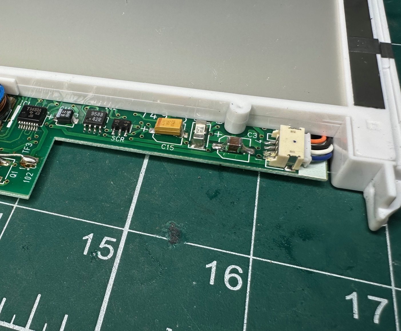
And finally, the inverter, with the brightness and contrast controls, which is connected in the middle to another PCB has the most leaking caps:
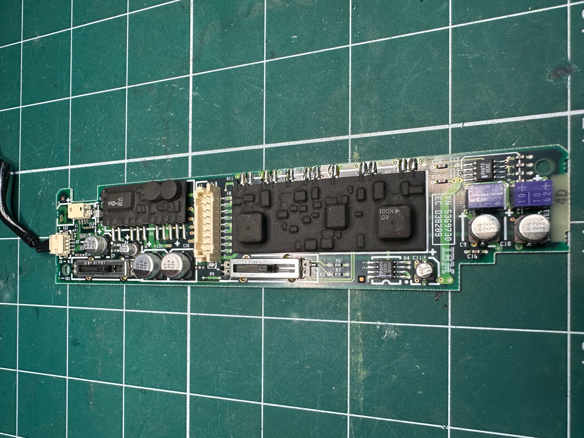
I replaced all my caps with solid ceramics or tantalums with no problem. Where possible I tried to keep the values as close as possible. Worth noting those two purple blocks are also electrolytic capacitors which are side-mounted.

Reinforcing Hinge Bases
I had some fun reinforcing the standoffs, within the machine's lid which frequenctly succumb to 30 years usage:


Finally, This one had a german keyboard and both the plastic tabs which hold it down to the base had snapped and long lost (as they often do). The keyboard generally still holds fast, but I did have a spare UK one which still had a damaged left side but good right side (and correct keyboard layout for me), so i swapped it in.
Dismantling
To dismantle the 755c is simple when you know how....
First remove the two black circles either side of the keyboard lift hinges and then remove the 2 screws underneath:

Then push a blade of spudger into either end of that black panel of plastic above the keyboard to help it push up
Unscrew the hinge cover on right and emove hinge cover on left.
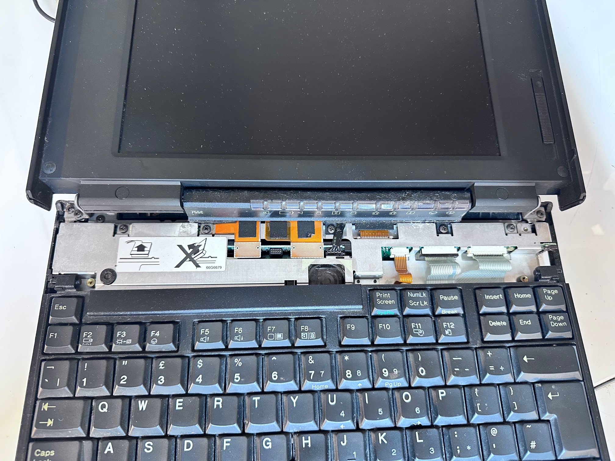
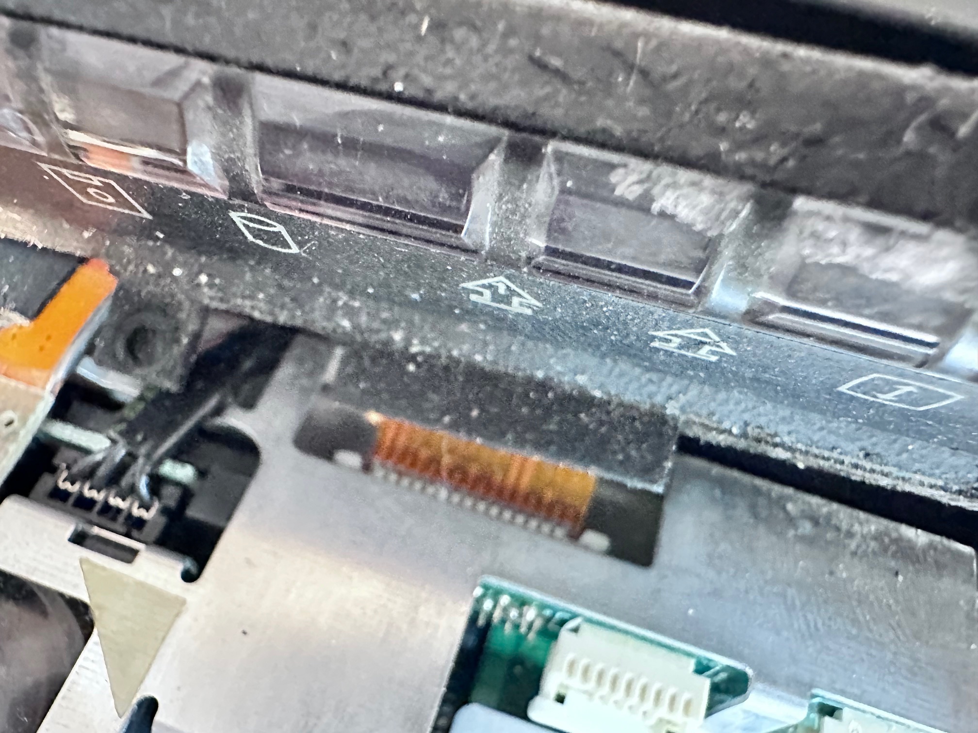
Release 3 ribbons to remove the keyboard:
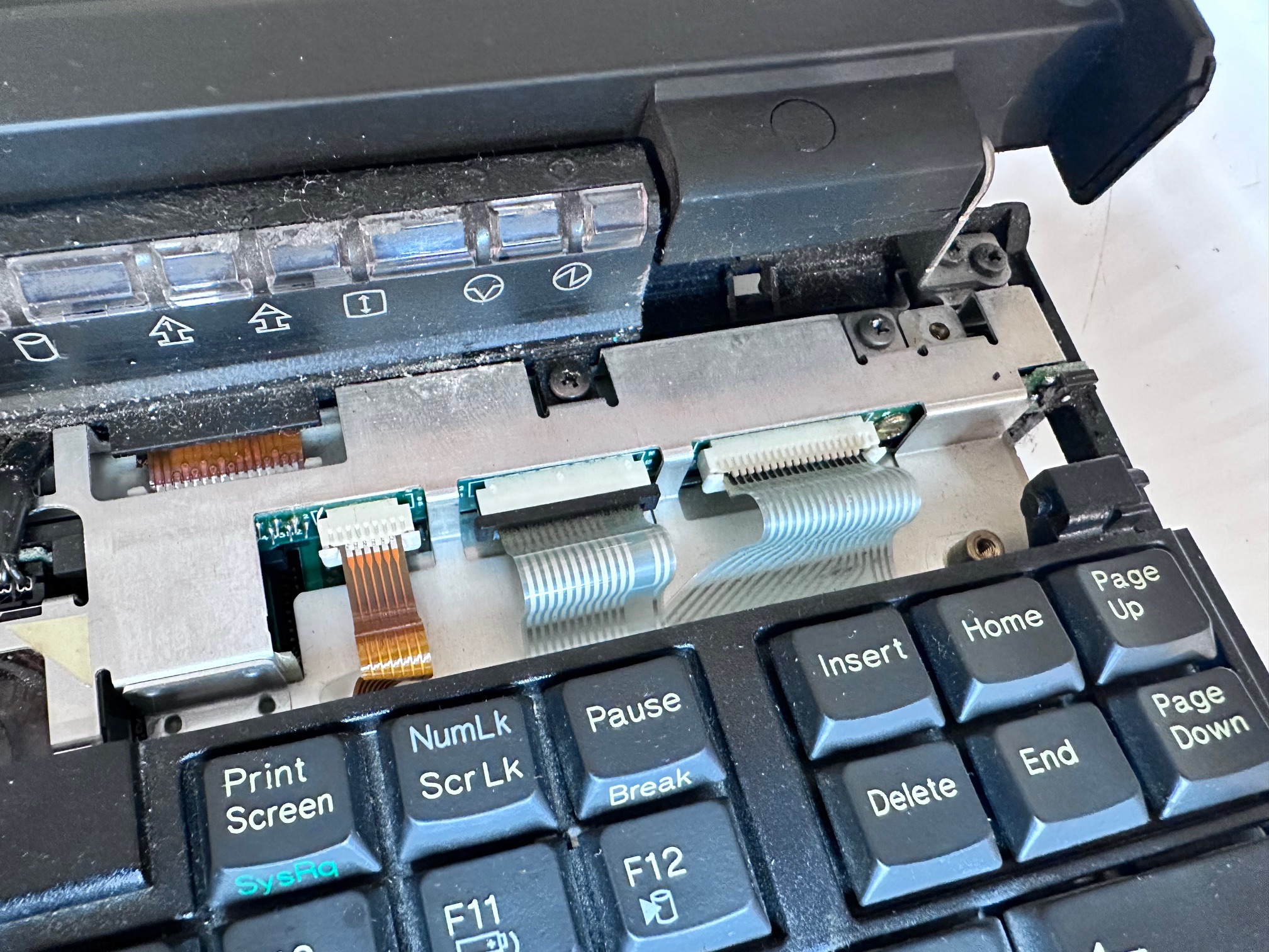
Unscrew the 3 screws holding down the LED bezel

The LED bezel has to be thumb-pushed from the back and a small piece of plastic pushed free from the front-left to release it and then you must release it's ribbon cable underneath.
Unscrew both hinge screws from both sides
Remove the screw in the base

Around the motherboard, remove
- 2 screws either side of floppy connector
- 2 long brass screws in the centre, above battery
- 2 screws either side of HDD
- 4 screws along the back

Remove top metal unplugging the speaker:

Watch for the white loose plastic spacer between Dc and motherboard:

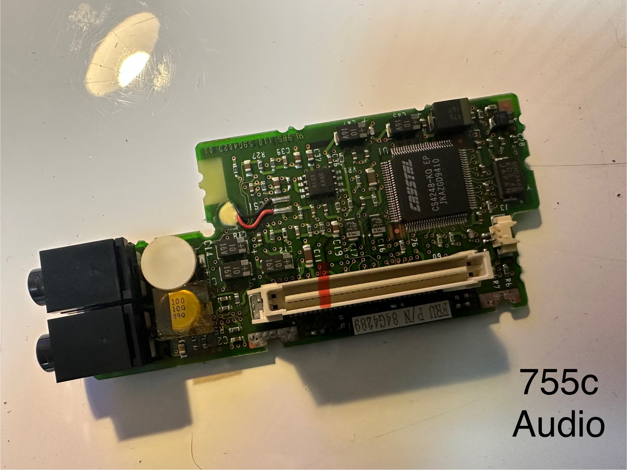
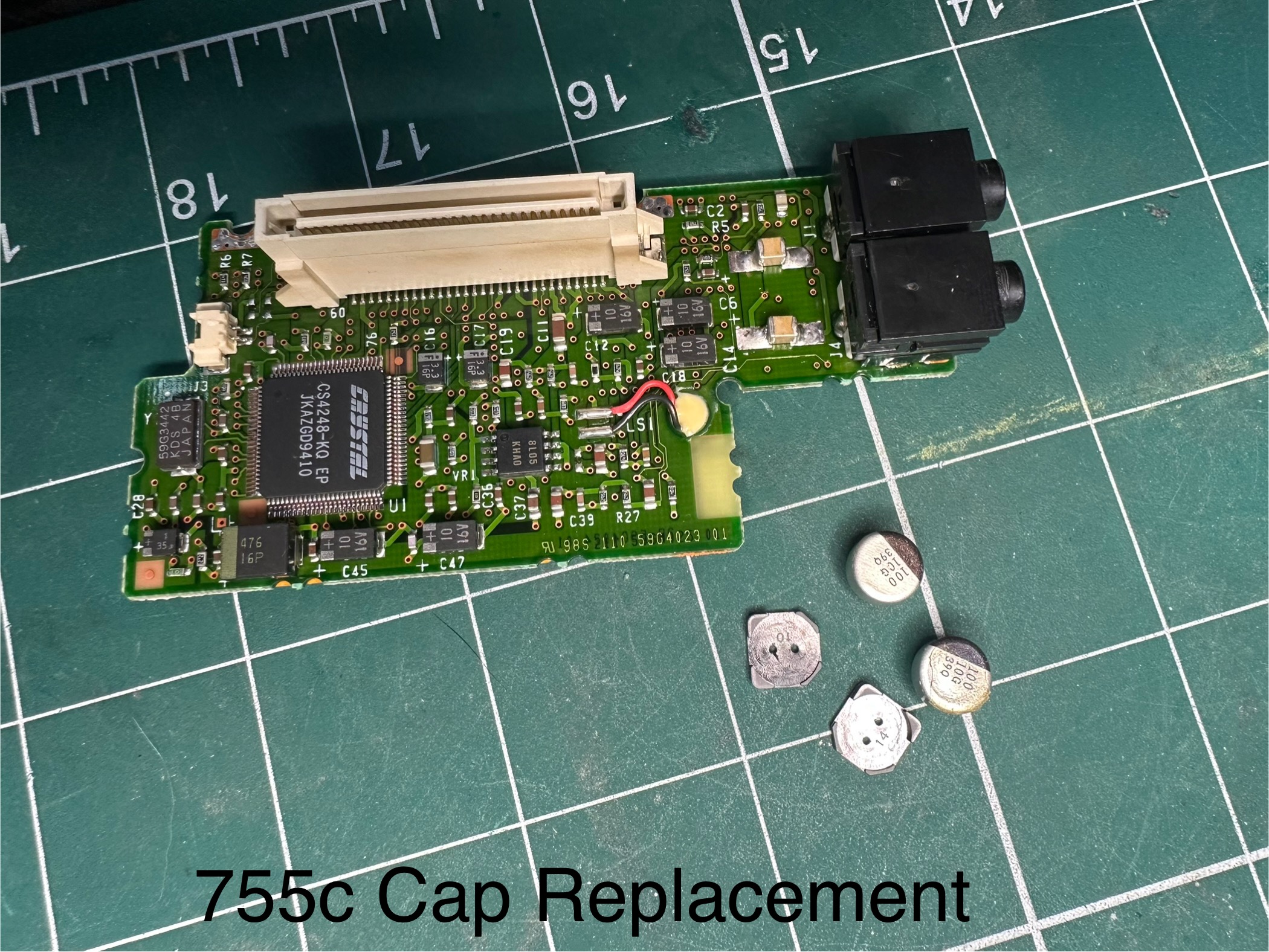
Pull off the soundboard

Pull off interposer

Remove the flat screw at the back holding the DC board down and carefully retain the black plastic spacer

The remaining motherboard will pull out but it’s held back by the on/off switch, the PCMCIA release buttons and a few other bits of plastic
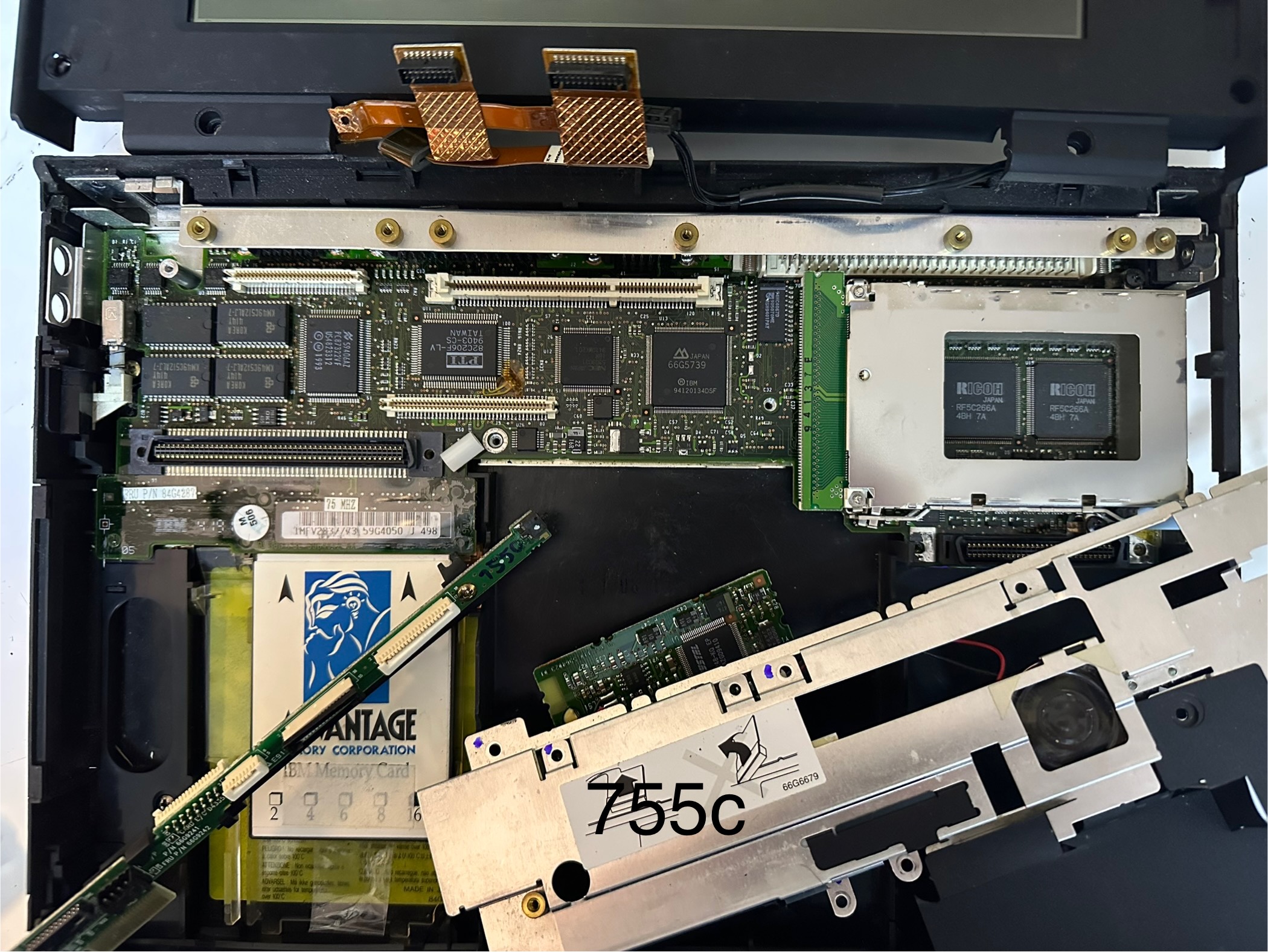
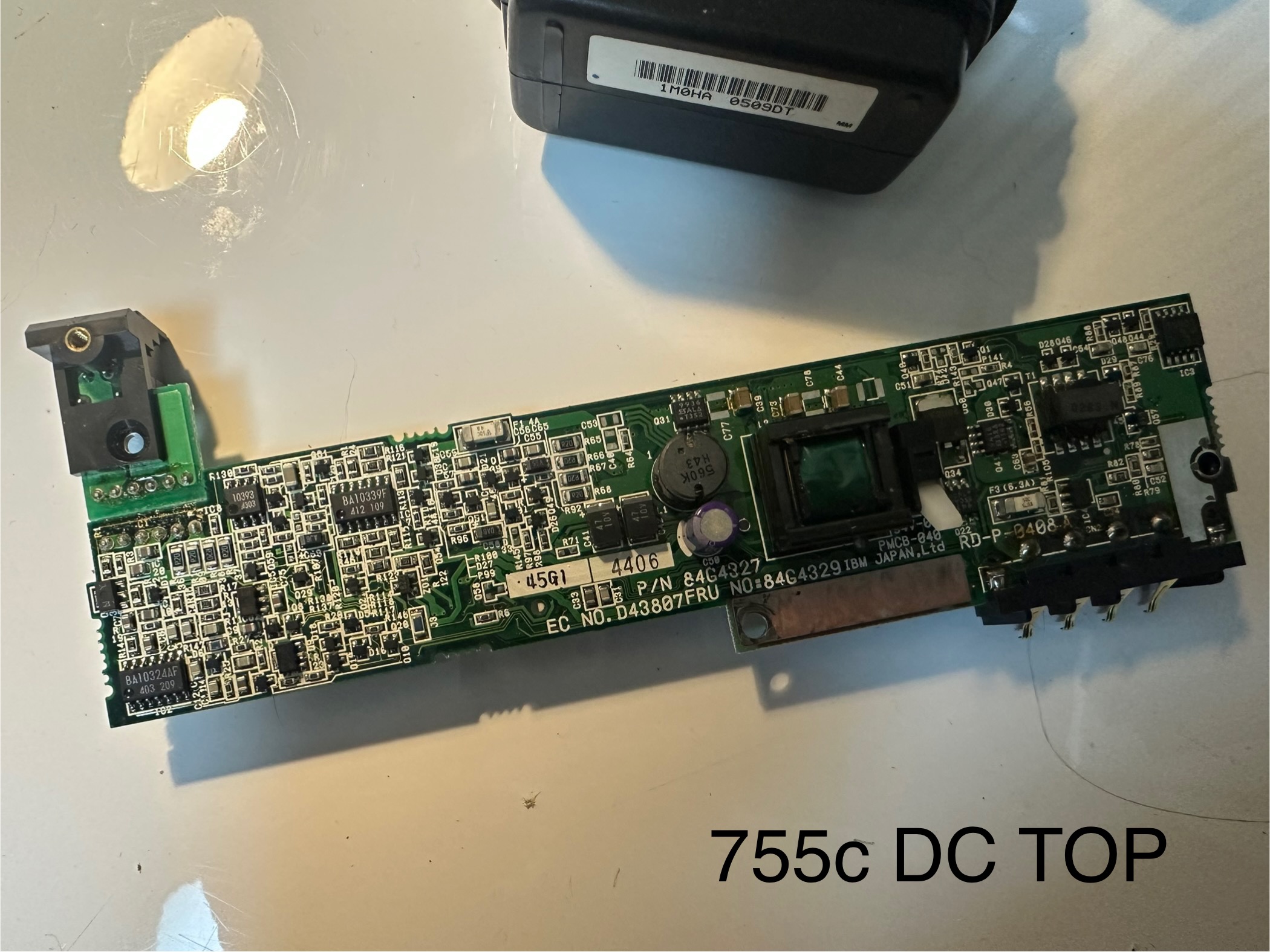
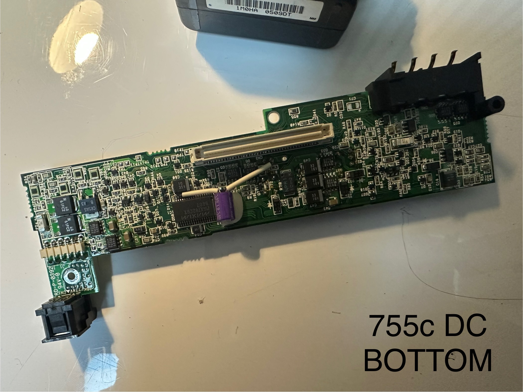
Some additional notes regarding the insides. Here are some pictures of the different boards:
Just for the sake of documenting it all, here is another 755c in my collection. A nice example...


Recreating PCMCIA Cover
On a lot of 755 machines, the PCMCIA cover is missing, and it's a different design to that found on the 760. So here is a very basic recreation:


